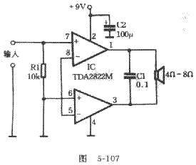
Generally, the integrated circuit has many peripheral components and requires a large heat sink. The power amplifier circuit introduced in this article is simple and easy to make. The circuit is shown in Figure 5-107. Using a TDA2822M power amplifier integrated circuit to connect to BTL mode, the peripheral components have only one resistor and two capacitors, no need to install a heat sink, and the playback effect is also satisfactory.
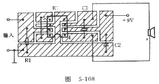
The integrated circuit TDA2822M is an 8-pin dual in-line package. If it is not available, it can be replaced by TDA2822. The package of TDA2822 is the same as TDA2822M. The difference is that TDA2822M can work from 3V to 15V, while the maximum operating voltage of TDA2822 is only 8V. To use TDA2822, the voltage must be reduced to below 8V. The value of R1 is not limited, generally choose 10k carbon film resistor. C1 can use 0.1uF polyester capacitor, C2 is 100uF / 160V electrolytic capacitor. Figure 5-108 is a diagram of its printed circuit board. Due to the simple circuit, the printed board can be made by scrubbing with water sandpaper or kraft paper dipped in a small amount of water, washed with water and dried, coated with a layer of rosin alcohol solution, and then dried directly to solder the components to the copper foil surface. After soldering, check to be correct, and then connect the power supply without connecting the speaker first, then the voltage between the positive and negative output terminals should be less than 0.1V. Connect the speaker and touch the input terminal with your hand. The speaker should emit a loud "buzzing" sound. At this time, you can input the signal sound test. The circuit board does not need to be drilled, 


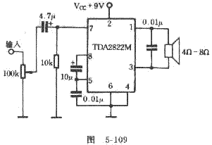
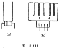
Please note when using: Because this power amplifier is directly coupled, the input signal must not have a DC component. If the input signal has a DC component, a capacitor of about 10uF must be connected in series at the input end, otherwise a large DC current will flow through the speaker, causing it to burn and burn. In practice, if the appropriate changes are made to Figure 5-107, the effect is more ideal. The improved circuit is shown in Figure 5-109. In use, it was found that the TDA2822M was hot when the volume was turned to the maximum, so a radiator was made for the TDA2822M, as shown in Figure 5-110. The radiator is made of aluminum sheet with a thickness of lmm, a length of 38mm, and a width of 25mm. And open 5 to 6 slots with a length of 10mm and a width of 1mm on the heat sink, and then fold the heat sink along the dotted line into a "mouth" shape. When installing the radiator, put some silicone grease on the TDA2822M (the silicone grease can be cut into the 3AX31 or 3AX81 tube shell). According to Figure 5-111 (a), it can be tied tightly with a thin wire. It should be noted that the pin number of TDA2822M is written on the side of the heat sink to avoid errors during soldering. After the radiator is added, the volume is turned to the maximum radiator and only a little warmer, the heat dissipation effect is good. This method can also be used for heat dissipation of other small integrated circuits. We use two power amplifier circuits to make a walkman stereo power connector to promote two small speakers, and the effect is very good.
In fact, where is your complexity, I directly connect the pipe corner, connect the speaker, the sound source, and add 6 ~ 12V DC to all OK. But with different sound sources and speakers, I found that the 2822 is fine. It's simple to do, and the cost is low, which is much stronger than the cheaper active speakers bought on the market.
Fast Recovery Diode (FRD) is a kind of semiconductor diode with good switching characteristics and short reverse recovery time. It is mainly used in electronic circuits such as switching power supply, PWM pulse width modulator and inverter, as high frequency Rectifier Diode. Use for freewheeling diodes or damper diodes. The internal structure of the fast recovery diode is different from that of a normal PN junction diode. It belongs to a PIN junction diode, which adds a base region I between the P-type silicon material and the N-type silicon material to form a PIN silicon wafer. Since the base region is thin and the reverse recovery charge is small, the reverse recovery diode has a short reverse recovery time, a low forward voltage drop, and a high reverse breakdown voltage (withstand voltage value).
Fast Diode,Fast Recovery Rectifier Diode,Fast Recovery Diode,Fast Switching Diode
Dongguan Agertech Technology Co., Ltd. , https://www.agertechcomponents.com