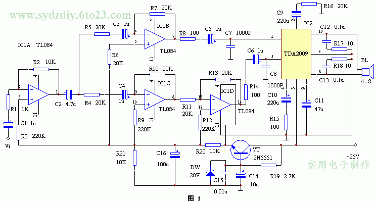
Here we introduce a BTL power amplifier circuit without debugging, high fidelity, and low cost, and can choose the final power amplifier integrated circuit according to your own situation. Due to its strong versatility, it brings great convenience to audio enthusiasts.
working principle

The list of components selection and debugging components is shown in the table below.
| Numbering | name | model | Quantity | Numbering | name | model | Quantity |
| R1 | resistance | 1K | 1 | C11 | Electrolytic capacitor | 47u | 1 |
| R2, 20, 21 | resistance | 10K | 3 | C12, 13 | Polyester capacitor | 0.1u | 2 |
| R3, R9, R12 | resistance | 220K | 3 | C14 | Electrolytic capacitor | 10u | 1 |
| R4ï¼R7, 10, 11, 13, 16 | resistance | 20K | 8 | C15 | Ceramic capacitor | 0.01u | 1 |
| R8, 14, 15 | resistance | 100Ω | 3 | C16 | Electrolytic capacitor | 100u | 1 |
| R17, 18 | resistance | 10Ω | 2 | DW | Zener diode | 20V | 1 |
| R19 | resistance | 2.7K | 1 | VT | Crystal transistor | 2N5551 | 1 |
| C1, 3, 4, 5, 6 | Electrolytic capacitor | 1u | 5 | IC1 | Four op amp IC | TL084 | 1 |
| C2 | Electrolytic capacitor | 4.7u | 1 | IC2 | Two-channel power amplifier IC | TDA2009 | 1 |
| C7, 8 | Ceramic capacitor | 1000P | 2 | BL | speaker | 4ï¼8Ω | 1 |
| C9, 10 | Electrolytic capacitor | 220u | 2 |
Due to the versatility of this circuit design, any dual power amplifier integrated circuit output by OTL or OCL can be connected to the B and C ends of the differential amplifier to form a BTL amplifier. If the reader is interested, you can also insert the RC attenuation tone control circuit, which will receive better results.

Follow WeChat
Interesting and informative information and technical dry goods

Download Audiophile APP
Create your own personal electronic circle

Follow the audiophile class
Lock the latest course activities and technical live broadcast
comment
Publish
related suggestion