Foreword
Recently, a circuit that controls the motor and measures the speed of the MSP430 microcontroller is being adjusted. The entire circuit was designed and debugged successfully. It took nearly four days, and there were a lot of bugs in the middle, but in the end it was solved.
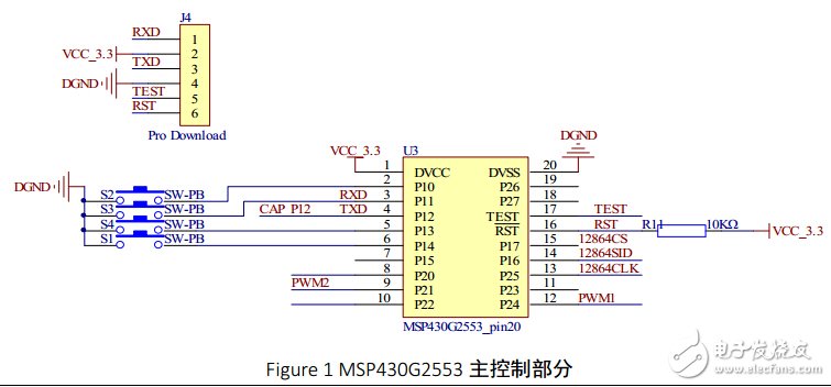
Not much nonsense, go directly to the topic, first talk about my system. Figure 1 below is the main control part of MSP430. The chip used is MSP430G2553 MCU (11, 12 pin is the reverse), the first one is Pro Download interface, as the name suggests, is the program download port, I use the launchPad of MSP430G series. The development board is connected to the board I designed. I can use the launchPad to download the program through these interfaces. In order to facilitate the wiring, I have disrupted the order of these interfaces. The PWM1 and PWM2 interfaces are the two interfaces connected to the H-bridge. Here, the timer A1 of G2553 is used to generate the PWM. CAP_P12 is a capture interface that is input to the MCU after the photoelectric pair is connected to the MCU. Because the capture interface of the timer A0 can be used here, the capture function of the timer can be used to make the program design simpler. The entire system utilizes two timers, combined with interrupts, so that the entire system is in a sleep state, power consumption can be made lower (but due to the existence of the motor and 12864, the low-power programming here is meaningless. . . . There is also a 12864 serial external interface (SPI) three wires.
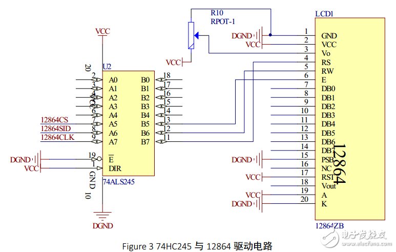
Then put a picture of three-line control 13864. Since the MSP430x2xx series is a 3.3V device, a 245 chip is used here to convert the level voltage (the order of CS and SCLK is reversed, and later changed when wiring). Beginners often encounter a problem, that is why my 12864 sliding rheostat is adjusted, and the brightness of 12864 is unchanged. I will only mention one point here: pay attention to the level of your reset pin.
The H-bridge circuit is too common, Baidu comes out and grabs a lot.
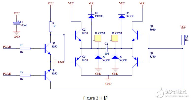
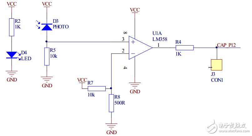
As for the principle of the H-bridge, I will not say more here. Do not understand Baidu, actually learned the triode, a little calm to analyze one, you can understand. The following is a comparator circuit, using the photoelectric to the tube to emit a signal, after the black line reflects a certain voltage value on the PHOTO, when the circuit is measured, the input voltage of the LM358 is as high as 0.6V (haha, in fact, not high... ), the right LM358 constitutes a comparator, VCC is 5V voltage, after 10K and 50 ohm resistor divider, the voltage of pin 2 of LM358 is about 0.5V<0.6V, which satisfies the circuit design requirements. After adding a 1K resistor to protect the latter microcontroller (haha, this resistor is convenient for me to filter later) Let's talk about the problem.
Kitchenaid Mini Chopper,Hand Food Processor,Large Food Processor,Best Food Chopper
JIANGMEN JIANGHAI DISTRICT SHENGHUI ELECTRIC CO.,LTD , https://www.shenghuielectric.com