Attention should be paid to the distortion problem when selecting a capacitor for any circuit. This type of distortion can occur if the capacitor is in the signal path. Figure 1 is a typical circuit with two capacitors in the signal path.
Figure 1a is the first stage of the Sallen-Key bandpass filter. In this circuit, two important capacitors appear in the signal path through the filter. Figure 1b is an amplifier that uses an R/C pair to drive a SAR-ADC. Capacitor CF is fully exposed to the input signal before it reaches the ADC.
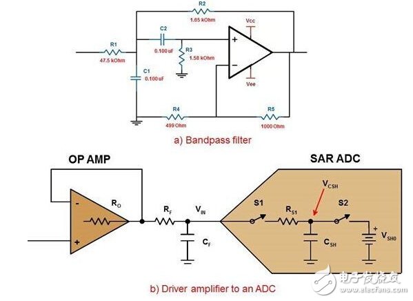
Figure 1. The first stage of the sixth-order bandpass filter (a) and the amplifier (b) that drives the ADC using the R/C pair.
The reason for this distortion is that the voltage of the standard capacitor is related to the characteristics. In other words, the capacitance varies with the applied voltage and frequency.
The following equations describe the change in capacitance over a voltage curve:
C=C0(1+bVCAP),
among them
C0 is the nominal capacitance
VCAP is the voltage of the entire capacitor
b is the voltage coefficient of the capacitor
Figure 2 is a typical plot of the effect associated with the entire capacitor.
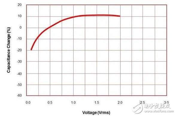
Figure 2. Capacitor voltage coefficient
A capacitor's input or output charge passes through adjacent impedances, creating a voltage drop error. Since the charging current of the capacitor is voltage dependent, a nonlinear error is generated. For sine waves, this error contains harmonics.
Capacitor voltage coefficient characteristics may be more apparent in semiconductor process technology. Since the ADC input (Figure 1b) has an internal input R/C, this distortion can also occur at the input of the converter.
In addition, the input signal frequency of the entire capacitor also affects the conversion accuracy. The capacitance value causes distortion and the distortion changes with frequency. (image 3).
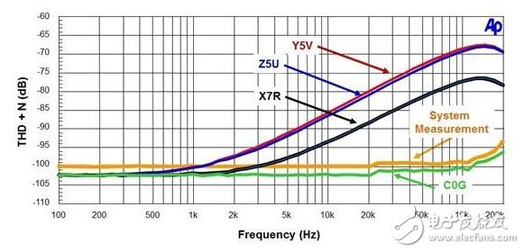
Figure 3. Comparison of capacitor THD+N and frequency
This figure is a comparison of several capacitor technical characteristics and their total harmonic distortion + noise (SINAD) versus frequency performance. The bottom curve in the figure is obtained using a C08 capacitor. The curve above the C0G capacitor data is the system measurement. The other curves in the figure are from ceramic capacitors with different dielectrics (Z5U, Y5V and X7R). Please note that these types of capacitors produce significant nonlinearities and signal distortion as a function of frequency.
The NPO type ceramic capacitor is not shown in the figure. NPO class capacitors match the C0G performance very well. The key is to choose the correct capacitor type for C1 and C2 (Figure 1a) and CF (Figure 1b). You will find that higher quality external capacitors (CF) do not degrade the AC performance standards of the ADC. The larger internal voltage coefficient of the smaller internal ADC capacitor (CSH) is not comparable to the lower voltage coefficient of the larger external capacitor.
There are many forms of signal distortion, but if such problems are encountered, the capacitors in the circuit signal path may be the last consideration.
This iPhone 6 Replacement Battery with TI IC have 100% compatiable with iOS lastest system. The battery with TI IC more safe, charge more faster, lasts longer life. To replace your faulty,defective,cracked,blister,leaking,jump percent battery,it perfect fit to your iPhone 6.
Nominal voltage: 3.82V
Limited charge voltage: 4.35V
Capacity:1810mAh (6.91whr)
Cell size: 33x39x96mm
iPhone 6 Replacement Battery,iPhone 6 Li-ion Battery,iPhone 6 battery with TI IC,iPhone 6 Li-ion Battery with TI,iPhone 6 Battery
Shenzhen Aokal Technology Co., Ltd. , https://www.aokal.com