OTL is shorthand for the English Output Transformer Less, which means no output transformer. An OTL power amplifier is a power amplifier circuit without an output coupling transformer. Most OTL power amplifiers use complementary push-pull output stage circuits.
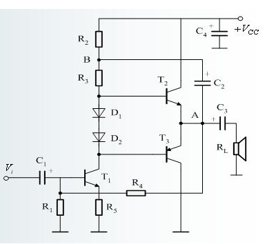
The figure shows a complementary symmetric OTL power amplifier circuit. T2 is an NPN power transistor, T3 is a PNP transistor, they constitute a complementary push-pull output tube, T1 is a voltage amplification excitation tube. After the signal is coupled through C1 and sent to T1 for amplification, T2 is turned on by the positive half cycle of the signal generated from the T1 collector, and turned on by the negative half cycle. The amplified signal passes through the capacitor C3 and is output to the speaker.
The capacitor C2 in the circuit is a bootstrap capacitor. It is composed of a bootstrap circuit with R2 and R3, so that the potential at point B increases with the increase of the output voltage, which expands the dynamic range of the circuit.
The OTL circuit is also called a no-output transformer power amplifier circuit. It is a power amplifier circuit that uses capacitive coupling between the output stage and the speaker without an output transformer. The main features are: using a single power supply, the output terminal DC potential is half of the power supply voltage; large capacitive coupling between the output and the load, one end of the speaker ground; with a constant voltage output characteristics, allowing speaker impedance 4Ω, 8Ω, Select from 16Ω, the maximum output voltage amplitude is half of the power supply voltage, ie 1/2 VCC, and the rated output power is approximately /(8RL).
The BTL circuit is also called balanced bridge power amplifier circuit. It is composed of two sets of symmetrical OTL or OCL circuits. The speaker is connected between the two groups of OTL or OCL circuit output terminals, ie the speaker is not grounded at both ends. The main features of the BTL circuit are: single-supply operation, equal DC potentials at both outputs, no DC current through the speaker, compared to OTL and OCL circuits, the BTL circuit output voltage can be the same under the same power supply voltage and the same load conditions. Doubled, the output power can be increased by a factor of four, which means that larger output power can be obtained at lower supply voltages. Transfer from 21ic basic knowledge
The difference between the two is as follows: The DC potential of the output terminal of the OTL power amplifier circuit is half of the power supply voltage. One end of the speaker is grounded, and the other end is connected to the output end of the power amplifier through a large-capacity coupling capacitor; the BTL power amplifier circuit uses two pairs of amplifiers, and the speaker is directly connected to the two. The outputs of the amplifier pairs do not require coupling capacitors.
China Phase Control Stud Thyristor,Stud Version Phase Control Thyristor supplier & manufacturer, offer low price, high quality Dc Power Encapsulation Thyristors,High Power Drives Thyristor Power Control, etc.
The output voltage of thyristor phase-controlled rectifier circuit can be regulated in a large range and has a small fluctuation, which has an impact on the electrical performance of ac power and devices.
Phase Control Stud Thyristor,Stud Version Phase Control Thyristor,Dc Power Encapsulation Thyristors,High Power Drives Thyristor Power Control
YANGZHOU POSITIONING TECH CO., LTD. , https://www.yzpst.com