When we use Zynq SoC or Zynq UltraScale + MPSoC in our design, there are two ways to implement the SPI interface:
Use the SPI controller on the PS side (there are two SPI controllers on the PS side)
Use AXI Quad SPI (QSPI) IP Module configured for standard SPI communication on the PL side
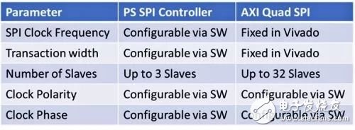
We can choose which method to implement the SPI controller according to the requirements of the application. Both SPI implementations support four SPI modes and can be used as either SPI master or SPI slave. The table below lists some of the differences between them:
First, we demonstrate how to use the SPI controller on the PS side for SPI transmission. The SPI controller is selected in the Zynq MIO configuraTIon tab, which includes the SPI in the design. In this example, I will connect the SPI signal to the SPI interface of the Digilent ARTY Z7 development board, which requires the use of EMIO via PL I/O.
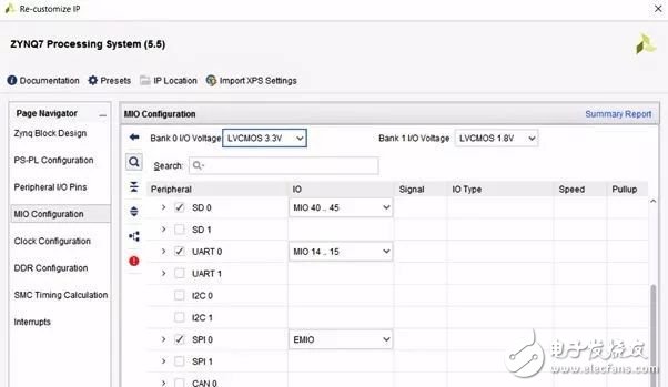
Figure: Enabling SPI and mapping ports to EMIO
After selecting the appropriate option, the only thing to do is to connect the I/O to the SPI port. How to connect depends on whether we need to configure an SPI master or slave. On the SPI controller, each SPI port has a corresponding available input (xxx_i) output port (xxx_o). The correct connection of the port is critical. If the connection is wrong, when you run the application, you will get a completely wrong result, which may take us a few hours to find the source of the problem. In addition, when configured as an SPI slave, there is an input called Slave Select; when used as an SPI master, there are three select pins.
When the I/O is properly configured and the project is created, we can configure the SPI controller as a master or slave using the SPI configuration option in the application. To configure and transfer data using the PS SPI controller, you need to use the API interface provided by the BSP (Board Support Package) defined by XSPIps.H. In the first example, we configured the SPI controller as an SPI master.
By default, SPI uses 8-bit transfers. However, we can also configure the transmission to be larger 16 or 32 bits. For 8-bit transfers, we can use the u8 data type in C programs. For 16-bit or 32-bit transfers, 16 or 32 bits are used to read and write the data.
In the beginning, this can cause some problems or generate compiler warnings, because the two data transfer API functions shown below need to send and receive buffers of data type u8:
S32 XSpiPs_Transfer(XSpiPs *InstancePtr, u8 *SendBufPtr, u8 *RecvBufPtr, u32 ByteCount);
S32 XSpiPs_PolledTransfer(XSpiPs *InstancePtr, u8 *SendBufPtr, u8 *RecvBufPtr, u32 ByteCount);
To solve the problem of using u16 and u32 data types, we need to convert the buffer to a u8 pointer as follows:
XSpiPs_PolledTransfer(&SpiInstance, (u8*)&TxBuffer, (u8*)&RxBuffer, 8);
This setup will allow us to transfer data that is 8, 16, or 32 bits in size. To demonstrate this setup, I connected the SPI master IO to the Digilent Digital Discovery pocket instrument to test the transmitted data. Use the above method to change the data width from 8 bits to 16 bits in the application software.
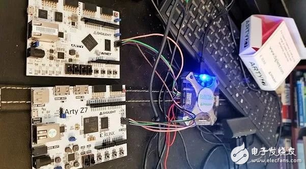
Figure: Arty Z7 development board with Digital Discovery pocket instrument
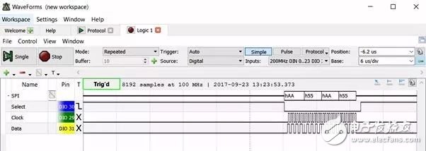
Figure: Zynq SoC PS SPI master sends four 8-bit words
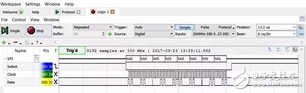
Figure: PS SPI master sends four 16-bit words
Another way to implement the SPI interface is to use the AXI QSPI IP core. This method requires a lot of setup in Vivado and takes a long time. In the AXI QSPI configuration dialog, we can configure the width, frequency, and number of slaves. The most important option is to choose whether the AXI QSPI IP core acts as an SPI master or slave. If you want to configure as an SPI master, you must check the enable master mode option. If you are configuring as a slave, you must deselect this option to ensure the presence of the SPISel input pin. When the SPI IP core acts as a slave, this pin needs to be connected to the slave select. port of the master.
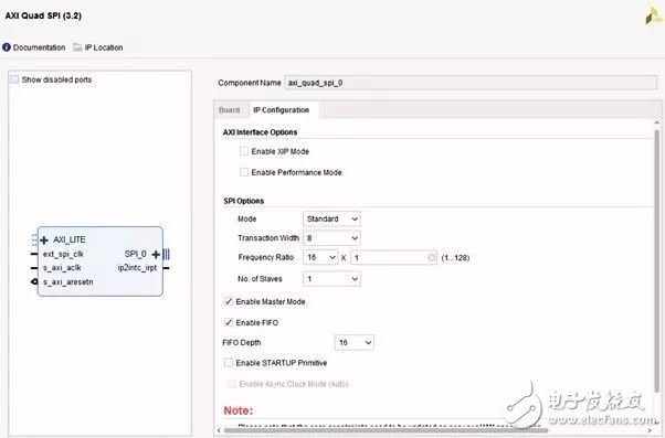
Figure: Configuring the AXI Quad SPI
Like the PS SPI controller, the BSP also provides an API interface for the SPI IP. We can use it to develop application software, this API is defined in the file XSPI.h. As a second part of the example, I will use this API to configure AXI QSPI as an SPI slave.
To demonstrate the creation of software, the AXI QSPI core can work correctly in SPI slave mode. I used the Digilent Digital Discovery pocket instrument again as the SPI master to transfer data between the two.
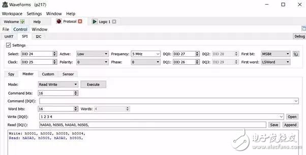
Figure: SPI slave device sends and receives data (blue data is output by Zynq SPI Slave)
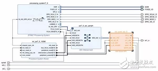
Figure: The final block diagram
Of course, if you use a Xilinx FPGA instead of a Zynq SoC or Zynq UltraScale MPSoC, you can use the MicroBlaze soft core with the same AXI QSPI configuration to implement the SPI interface. Just define it correctly as a master or slave.
I hope this article will help you understand how to create a master/slave SPI interface using these two different methods.
What is a Mobile Phone Back Skin?
The Mobile Phone Back Sticker is an interesting way to decorate the phone, which can add style to the mobile phone while also providing a small amount of protection. They are different from Mobile Phone Cases, which usually pay more attention to function than style. The Back Sticker is directly attached to the surface of the phone, which can achieve a more unique appearance than most phone cases.
Sometimes called skin or Mobile Phone Case, the typical mobile phone Back Film is made of vinyl products. The material provides a glossy finish and can use a variety of colors in the design. JJT can provide you with a variety of solid colors or use a variety of different patterns and color combinations of skins. In all cases, the Back Film is close to the phone body and will not interfere with any functions of the phone.
One of the advantages of using decorative skins is that they will not be permanently attached to the phone. This means that you can choose several different Back Skin Sticker and change the appearance of the phone according to the occasion. For example, they can be used to decorate mobile phones during holidays, seasons of the year, or special events such as birthdays, wedding receptions, and any other imaginable occasions.
Whether you want to get gorgeous, high-density, high-quality skin for your smartphone, then you need 3D Relief Back Sticker to fit your phone perfectly. Abandon the bulky Phone Case and wrap the smartphone in a high-quality PVC Back Sticker.
The Back Sticker not only adds texture to your smartphone for a strong anti-skid feel. It also hides the cracks on your back smartphone without having to add a bulky case or pay a huge sum to replace it.
Precise cutting and long-lasting durability: The Back Sticker Cutting Machine can perform precise cutting, is compatible in all situations, and the hole position is accurate, which is very suitable for your equipment.
Zero air bubbles, no residue: The Back Skin has excellent air permeability and a slim appearance, and will not leave any residue after being torn off, so it will not affect the wireless charging function.
Anti-scratch and anti-fingerprint: Mobile Phone Back Wrap uses PVC environmentally friendly materials to protect your phone from daily scratches, dust, scratches and normal wear and tear. Provide a protective back for the phone (including curved edges).
Mobile Phone Back Stickers,3D Relief Back Sticker,Back Film Cover Sticker,Screen Protector Back Film Cutting Machine
Shenzhen TUOLI Electronic Technology Co., Ltd. , https://www.hydrogelprotectors.com