The power line carrier communication uses the power line as the signal transmission channel to complete the engineering “last mile access†communication needs. Since the power line carrier is accessed using the power supply line required by most of the electrical appliances, there is no need to provide additional dedicated communication lines, which has a strong advantage in user convenience, installation and construction and circuit cost savings.
This article proposes a building automation system based on the power line carrier and mesh automatic networking technology for this problem. Because the power line carrier technology uses the existing power line as the medium for information transmission, this not only can save the user from installing the system's wiring troubles, but also Post-maintenance will also be easier and have better prospects.
2 System Description2.1 System Physical Topology
Power line carrier-based communication systems use power lines on communication physical lines. Due to the characteristics of power lines, the network topology is a typical bus network. The topology is shown in Figure 1.
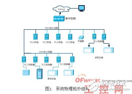
The terminator directly connected to the controlled device will play the role of a slave. The user terminal forms a bus-type LAN through the power line and other terminals, and the other end is a connection of various detection and control quantities. A centralized controller is installed in each building or within a small area, and then equipped with a pc or a computer terminal, so that building management personnel can centrally collect information or manage it.
2.2 System Software and Hardware and Network Stack Model
The building automation system is actually a typical computer communication system. The design tasks of this paper are mainly based on power line communication technology controlled node controller, power line communication network relay, and power line gateway with pc interface. It involves hardware and software design and network technology. This system uses the reference osi reference model and according to the actual situation to modify and reduce the method to design the network stack, network stack model shown in Figure 2.
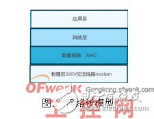
The physical layer uses a civilian 220v power line. Data link layer processing channel contention and collision detection. Mac, in view of the characteristics of the power line carrier, add a node-like information transmission mechanism similar to the wireless network at the data link layer, and cooperate with the network layer to implement automatic networking, namely mesh network technology. This design is conducive to the debugging and installation of node communication terminals, and can be plug and play. Because the data traffic of the building automation system is not large, the network technology based on the power line also simplifies the network topology to some extent, so does not need to realize the very complicated network layer and the transmission layer. Data transmission control checks can be implemented at the application level as needed. This is more conducive to reducing the complexity of the system, and the corresponding increase in reliability.
3 Hardware Design3.1 System Hardware Structure Design
This system involves three types of hardware, power line communication controllers, power line relays, and Ethernet bridges. The power line communication controller (plc controller) and the repeater hardware structure are the same. The difference is the software function support. The Ethernet bridge has more Ethernet extensions than the plc controller, but less communication with the controlled device. Figure 3 shows the system hardware network structure.
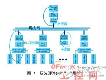
As described in Fig. 3, in this system, the mi200e modulation and demodulation and the control output of stm32 and stm32 hardware io constitute a plc controller; a repeater composed of mi200e and stm32mcu is used to extend the network after the signal is attenuated; the solution is modulated by mi200e Tuning circuit, stm32mcu and enc28j60 constitute power line to ethernet/internet bridge, constitute a complete network hardware system.
3.2 Communication Terminal Design
The communication terminal hardware structure is shown as 4. The communication terminal uses mi200e power line carrier dedicated chip and arm cortex MCU stm32 f103c8t6 interface, so that the system protocol is easy to modify and upgrade for the application. The stm32 f103c8t6 is a 32-bit arm cortex-m3 single-chip microcomputer with a relatively high computing capability, a clock speed of 72mhz, and a rich hardware interface.
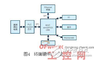
The system also has io,ad input and output interfaces with external controlled devices. Simultaneously using spi to expand the Ethernet chip is convenient to use as an Ethernet bridge. At the same time, the system has an rs232 interface output that can be connected to the pc, or as a debug or Expanded to 485 and other bridges.
3.3 mi200e transmit coupling circuit
The function of the transmission coupling circuit is to encode and modulate the data transmitted by the single-chip microcomputer, and then the power is amplified and then coupled to the 220v high-voltage circuit, as shown in FIG.
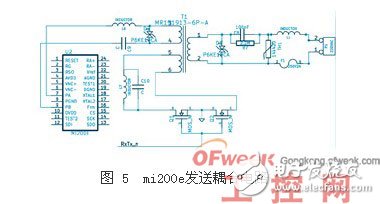
Because the mi200e comes with its own modulation, filtering, digital amplifier circuit, so the peripheral circuit is simple. After mi200e's power amplifier outputs pa and pb are output, the lc passive band-pass filter composed of l6 and c9 is filtered and then sent to the signal coupling transformer, and then transmitted through the coupling transformer to the 220v power line path. Here focuses on the part of the next coupling transformer circuit, because 220v is a dangerous personal power, and the output of mi200e is a weak signal of 10vpp, so the coupling transformer has two roles here, one is its primary and safety capacitor c8 constitute a high-pass filter , Interrupt 50hz frequency signal, to ensure the safety of the chip circuit, another role is that the secondary and peripheral circuits constitute a bandpass filter at the same time, help to modulate the signal selection. In addition, the circuit rxtx_n in the figure controls the switching circuit formed by two mos tubes. This part of the circuit helps to improve the waveform of the signal when mi200e is sent. The two tvs tubes of d1 and d2 in the coupling circuit limit the signal amplitude to a certain range, which has a protective effect on the subsequent circuit. R7 helps the safety capacitor discharge when it is powered off to ensure safety. Th1 is a varistor, which can help absorb current when the signal at both ends of the impact is large, so as to protect the small-signal circuit in the subsequent stage from being damaged by the 220V impact voltage.
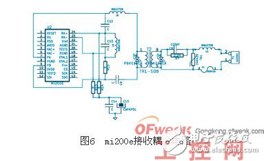
3.4 mi200e receive coupling circuit
As shown in Fig. 6, the receiving circuit is responsible for extracting the modulated signal on the line, and then sending it to ra+ of mi200e and demodulating both ends of ra-. Since the signal coupling part is shared with the transmission part, only a simple lc band-pass filter is needed to send it to mi200e. The signals sent by the signal coupling transformer are sent directly to the mi200e 23 and 24 pins after being passed through the band-pass filters formed by c13 and l9, and then enter the chip for demodulation.
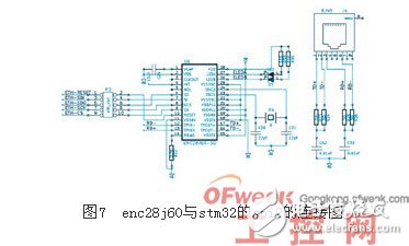
3.5 spi extended Ethernet circuit
System and Internet Communication Select Microchip's spi interface for external Ethernet expansion. The enc28j60 includes a 10 mbps Ethernet physical layer device (phy) and media access controller (mac). It can reliably send and receive information packets according to the industry standard Ethernet protocol. , with programmable filtering. Special filters, including microchip's programmable pattern matching filters, can automatically evaluate, receive, or reject magicpacket, unicast, mulTIcast, or broadcast packets to relieve the host microcontroller Processing load. Programmable 8kb dual-port sram buffers store, retrieve, and modify information packets in an efficient manner to ease the memory load of the host microcontroller. The buffer memory provides a flexible and reliable data management mechanism. The enc28j60 is connected to the spi2 of the stm32, and the circuit is shown in FIG.
4.1 mi200e packet transceiver
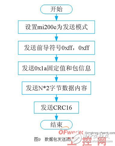
The mi200e data packet has a basic format. The data packet is firstly a two-byte 0xff preamble, followed by 0x1a and packet length information, followed by a two-byte multiple data area, and finally a two-byte crc16 school. Verification, checksum Verification of data after 0x1a, including packet information and specific packet data content (see Figure 8).
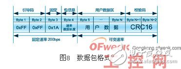
The mi200e performs data transmission every 10 ms. In order to establish data communication in a stable manner, byte 1 to byte 4 use a lower rate of 200 bps for data transmission. The first 4 bytes contain the boot code, the baud rate used for subsequent transmissions, and the data length. After sending these 4
After byte, the transmit baud rate can be changed by reconfiguring the mode register. At a rate of 1600 bps, one word of data will be sent every 10 ms. Since pkg_length in byte 4 occupies 6 bits, the data length of each packet should not exceed 64 words. The data packet sending process is shown in Figure 9.
When the mi200e is in the receiving state, it is necessary to repeatedly query the ri, carr, and frame flags of the status register (0x82). After the carr and frame are set to '1' by hardware, first read the receive mode register (0x83), remove the package information (baud rate and data length), and write the received baud rate information to the mode register (make the transmit and receive both The baud rate of the end is the same), and then receive according to the data length obtained, the ri, carr, and frame flags need to be queried each time a word data is read, and only the ri, carr, and frame are set to "1" by the hardware. Next, read the received data in mi200e again. After reading all the data, query the crc flag in the status register (0x82) to determine if the data has been received correctly. The process of receiving data packets is shown in Figure 10.

Figure 10 packet reception flow chart
4.2 enc28j60 network driver design
This system adopts enc28j60 Ethernet control chip, and needs to write network device driver to realize low-level network interface and hardware function driver. This driver mainly completes the initialization process of the enc28j60 network chip, completes the configuration information of the enc28j60 network card chip loaded in the stm32 controller, and performs the self-check function of the enc28j60, as shown in FIG.
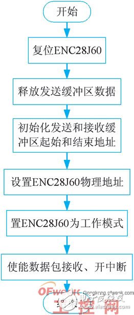
Figure 11 enc28j60 network driver flowchart
4.3 Data Link Layer Design
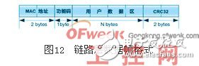
The mi200e provides basic packet structure and carrier sense. This feature mimics the design of ieee802.3mac. Here, the mac address of the node is added to the mi200e data packet, and at the same time, since it is for the control application, the function description code for the data content is arranged behind the mac address, for quickly obtaining the current communication, and it is convenient to distinguish the broadcast data without the instruction data responding. And need to respond to the instruction data. Behind the description code is the specific data content. Due to the extensiveness of the power line and the need for building control security, the data content can be encrypted using an encryption algorithm such as aes128, and crc32 check can be performed on the content at the same time to further provide reliability and security. The link layer data frame format is shown in Figure 12. The design of the link layer data frame format provides the ability to distinguish between nodes. With mi200e's frame detection mechanism, the Ethernet bus can be used to effectively solve the line contention problem. Link layer data frame format.
4.4 Network layer design (mesh)
Due to the inherent characteristics of the power line, the communication of the power line is very similar to the channel characteristic of the wireless network, and the signal will inevitably have a relatively large loss after a period of the line, so the carrier signal cannot be received after a certain distance, and the signal Coverage is a range. This is similar to wireless network access to wifi and zigbee. At the same time, due to the time-varying impedance of the power line, the nodes are not very stable in the network and may be able to communicate for a while. Nodes, this is similar to the wireless signal volatility, so consider adding the routing feature of the mesh mechanism at the network layer, can greatly increase the coverage of communications, can be used to form a relatively large network, to meet the application of the current social large-scale buildings demand.
5 Concluding remarksAfter actual hardware production and program testing, the system has good scalability. Based on the carrier sense mechanism of mi200e, the network has a faster response speed and is more efficient than the polling mechanism of modbus. Because of adopting mesh technology, network installation and configuration It's easier and the coverage can be extended to a few hundred meters. In addition, there are bridge applications that can be easily connected to the Internet.
Idc Connectors,Idc Socket Connector,Idc Electronic Socket Connector,2.00Mm Socket Connector
Dongguan Yangyue Metal Technology Co., Ltd , https://www.yyconnector.com