1. Problems in selection. Some vortex sensors have larger selections in the caliber selection or after the design selection due to changes in process conditions. The actual selection should select the smallest possible caliber to improve the measurement accuracy. The main reasons for this are the same Questions â‘ , â‘¢, â‘¥ are related. For example, a vortex pipeline is designed to be used by several devices. Due to the sometimes unused parts of the process, the current actual flow rate is reduced. The actual use causes the original design to be too large, which is equivalent to increasing the measurable flow rate. The lower limit, the indication cannot be guaranteed when the flow rate of the process pipeline is small, and it can be used when the flow rate is large, because sometimes it is too difficult to re-modify. Changes in process conditions are only temporary. It can be combined with the re-setting of parameters to improve the indication accuracy.
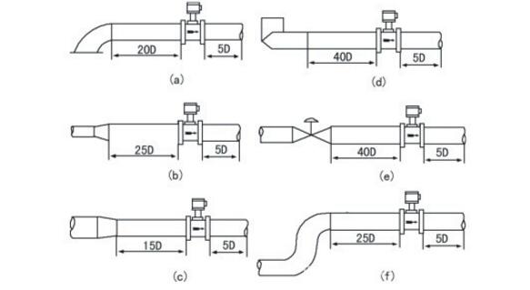
2. Problems with installation. The main reason is that the length of the straight pipe section upstream or downstream of the vortex flowmeter sensor is not enough (see the following figure for specific requirements), which affects the measurement accuracy. This reason mainly causes failure a.

3. The reason for the parameter setting direction. Due to wrong parameters, the indicator of the instrument is wrong. The parameter error makes the calculation of the full-scale frequency of the secondary instrument incorrect. The reason for this is mainly related to the problems â‘ and â‘¢. The similar full-scale frequency makes the indication inaccurate for a long time. The actual full-scale frequency greatly calculates the full-scale frequency so that the indication fluctuates widely and cannot be read, and the inconsistency of the parameters on the data affects the final determination of the parameter. Recalibration and comparison with each other determine the parameters to solve this problem.
4. Secondary instrument failure. There are many faults in this part, including: once the circuit board of the instrument is disconnected, the individual bit display of the range setting is broken, and the individual K bit setting is broken, making it impossible to determine the range setting and the K factor setting. Part of the reason is mainly related to questions â‘ and â‘¡. By repairing the corresponding fault, the problem can be solved.
5. Four-way line connection problem. On the surface of part of the circuit, the line connection is very good. Careful inspection. Some of the connectors have actually been loosened, causing the circuit to be interrupted. Although some of the connectors are tightly connected, the fastening screw is tightened on the wire due to the problem of the auxiliary line, which also makes the circuit Interruption, this part of the reason is mainly related to problem â‘¡.
6. The connection between the secondary instrument and the follow-up instrument. Due to the problem of the follow-up instrument or the maintenance of the follow-up instrument, the mA output circuit of the secondary instrument is interrupted. For this type of secondary instrument, this part of the reason is mainly related to the problem â‘¡. Especially for the follow-up recorder, when the recorder is damaged for a long time and cannot be repaired, it is necessary to pay attention to short-circuit the output of the secondary instrument.
7. Due to the failure of the flat shaft cable of the secondary instrument, the loop has no indication at all times. Due to the long-term operation, coupled with the influence of dust, the flat-axis cable malfunctions, and the problem can be solved by cleaning or replacing the flat-axis wire.
8. For the problem ⑦, it is mainly due to the loosening of the fixing screws of the coil of the display head of the secondary meter, which causes the head to sink, the pointer and the case friction is large, and the action is not effective. By adjusting the head and re-fixing, the problem is solved accordingly.
9. Environmental issues. Especially for the sensor part installed in the ground well, due to the high humidity of the environment, the circuit board is damp. This part of the reason is mainly related to the problem â‘¡, â‘¡. Through corresponding technical reform measures, some sensors with high ambient humidity were re-separated from the probe part and the conversion part, and a separate sensor was used. Therefore, the working environment was improved, and this part of the instrument has been operating well.
10. Because the on-site adjustment is not good, or because of the actual changes after adjustment. Due to poor vibration and noise balance adjustment and sensitivity adjustment on site. Or due to the changes in the on-site situation after a period of operation after the adjustment, the indication problem is caused. This part of the reason is mainly related to the problems ④ and ⑤. Use an oscilloscope, combined with the operating conditions of the process, readjust.
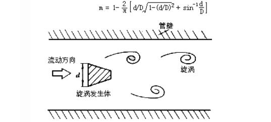
Working principle of vortex flowmeterA vortex generator (blocking fluid) is provided in the fluid, and regular vortices are alternately generated from both sides of the vortex generator. This vortex is called Kaman vortex street, as shown in FIG. 1. The vortex array is arranged asymmetrically downstream of the vortex generator. Suppose the frequency of the vortex is f, the average velocity of the incoming flow of the measured medium is U, the frontal width of the vortex generator is d, and the surface diameter is D. According to the Kaman vortex principle, the following relationship
f = SrU1 / d = SrU / md (1)
In the formula, U1--the average flow velocity on both sides of the vortex generating body, m / s;
Sr-Strouhal number;
m--the ratio of the arcuate area on both sides of the vortex generating body to the cross-sectional area of ​​the pipe

Figure 1 Kaman vortex street
The volume flow qv in the pipeline is
qv = πD2U / 4 = πD2mdf / 4Sr (2)
K = f / qv = [Ï€D2md / 4Sr] -1 (3)
In the formula, K--meter coefficient of flowmeter, pulse number / m3 (P / m3).
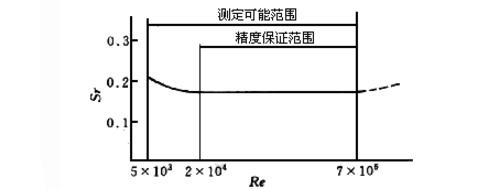
K is related not only to the geometrical dimensions of the vortex generator and the pipeline, but also to the Strouhal number. The Strouhal number is a dimensionless parameter, which is related to the shape of the vortex generator and the Reynolds number. Figure 2 shows the relationship between the Strouhal number of the cylindrical vortex generator and the Reynolds number of the pipeline. It can be seen from the figure that in the range of ReD = 2 & TImes; 104 ~ 7 & TImes; 106, Sr can be regarded as a constant, which is the normal working range of the instrument. When measuring the gas flow rate, the calculation formula of VSF flow rate is


Fig. 2 Relationship curve between Strouhal number and Reynolds number
In the formula, qVn and qV--respectively are the volume flow rate under standard conditions (0oC or 20oC, 101.325kPa) and operating conditions, m3 / h;
Pn, P--respectively the absolute pressure under standard conditions and operating conditions, Pa;
Tn, T--respectively the thermodynamic temperature under standard conditions and working conditions, K;
Zn, Z--respectively the gas compression coefficients under standard conditions and operating conditions.
It can be seen from the above formula that the pulse frequency signal output by the VSF is not affected by changes in fluid properties and composition, that is, the instrument factor is only related to the shape and size of the vortex generator and the pipeline within a certain Reynolds number. However, as the flowmeter needs to detect the mass flow rate in the material balance and energy measurement, the output signal of the flowmeter should monitor the volume flow rate and the fluid density at the same time, and the fluid properties and components have a direct impact on the flow measurement.
Vortex flowmeter parameter setting methodParameter setting is an important task for the use of flowmeters, and Hehe introduces you to the parameter setting steps of vortex flowmeters:
Vortex flowmeter key definition and parameter setting:
Key definition:
1 key-used to store and turn to the next item.
2 keys-for left shift of data (for parameter setting).
3 key-used to increase the last digit of data by 1 (for parameter setting).
parameter settings:
Press and hold the 1 and 2 keys at the same time, then release, the meter displays:
1 item: 0 0 0 0 0 Pass Press 1 to display the next item
2 items: liquid, gas, saturation, overheating, press 3 key, select one item, press 1 key, the next item is displayed
3 items: Flow rate Nkgm3t / h (optional one of m3 / h, t / h, kg / h, km3 / h, Nm3 / h, Nkm3 / h)
Cumulative Nkgm3t (optional one of m3, t, kg, km3, Nm3, Nkm3)
Press the 3 key to select one of the items, press the 1 key to display the next item
4 items: 0.0 0 0 (instrument factor, on the sign) quo
Use 2 and 3 key combination to input (see key definition) data, press 1 key to next item
5 items: Frequency 0.0Hz (small signal cut-off value) The setting method is the same as 4 items, the next is the same, press 1 key to the next item
6 items: Pressure 0.000Mpa (gauge pressure), the temperature and pressure integrated plate has this item set, press 1 key to the next item
7 items: temperature 0.0 ℃, this item is available for temperature and pressure integrated board. Set up, press 1 to go to the next item
8 items: Density 0.000kg / m3 is set, press 1 to go to the next item
9 items: 0.000 Nkgm3t / h (20mA corresponds to full-scale flow value),
Battery-powered without this item Full set, press 1 key to the next item
10 items: Accumulative 0.0 Nkgm3t / h Press 2 and 3 simultaneously to clear 0, and finally press to exit the parameter setting
Supplementary explanation of parameter setting:
1. Temperature, pressure, density
The density of superheated steam and saturated steam is calculated based on the temperature and pressure values. However, if the density value (8 items) is set to a fixed value (not 0), the density value is set regardless of the temperature and pressure values. Value, instead of the value calculated based on temperature and pressure, if automatic compensation is required, please reset the density value to 0. In addition, the data in the temperature (7 items) value and pressure (6 items) value is set to a fixed value (not 0), Then, display the temperature and pressure according to the set value, and calculate the corresponding density. If you need to automatically obtain the temperature and pressure from the sensor, you must clear the temperature and pressure value to 0.
2. In saturated steam and superheated steam
When you are sure that the medium is saturated steam, please select saturation in 2 items. When you cannot judge whether the medium is superheated steam or saturated steam, or when the medium is switched back and forth in two states of superheated steam and saturated steam, please select 2 Overheating, the instrument will automatically determine whether the medium is superheated steam or saturated steam, and calculate the corresponding density to compensate.
3. About 4ã€8ã€9 parameter setting methods
Example: Set the meter factor 12345.6 in 4 items
Press the 2 key multiple times until it becomes 0.000,
Press the 3 key once, it becomes 0.001
Press the 2 key once, it becomes 0.010
Press the 3 key twice, it becomes 0.012
Press the 2 key once, it becomes 0.120
Press the 3 key 3 times, it becomes 0.123
Press the 2 key once, it becomes 1.230
Press the 3 key 4 times, it becomes 1.234
Press the 2 key once, it becomes 12.340
Press the 3 key 5 times, it becomes 12.345
Press the 2 key once, it becomes 123.450
Press the 3 key 6 times, it becomes 123.456
Press the 2 key once, it becomes 1234.56
Press the 2 key once, it becomes 12345.6
After setting, press 1 to save.
4. On-site temperature fine-tuning method
Press the 1 and 2 keys at the same time to display 00000 (the word PASS is displayed in the lower row), enter 119, press 1 to turn the page, the upper row displays the temperature 0.0, and the temperature adjustment range is -25.5 to + 25.5 ° C. When setting, the symbol is not considered first , Press the 3 key, the temperature compensation value increases, press and hold the 2 key, then press the 3 key, the temperature compensation value decreases, after setting the number, press the 2 key to switch the symbol, no sign means positive compensation, negative sign means negative compensation, Then press 1 key to exit without adjustment, set to 0.0. For example, the field instrument display temperature is 100.0 ℃, the actual pipeline temperature is 105.1 ℃, the set temperature is 5.1 ℃, and there is no sign.
5. On-site pressure fine-tuning method
Press 1 and 2 at the same time to display 00000 (PASS is displayed in the lower row), enter 110, press 1 to turn the page, the upper row displays the pressure 0.000, and the pressure adjustment range is -0.255Mpa to + 0.255Mpa. When setting, do not consider Press the 3 key to increase the pressure compensation value. Press and hold the 2 key first, then press the 3 key to decrease the pressure compensation value. After setting the number, press the 2 key to switch the symbol. Unsigned means positive compensation and negative sign means negative compensation , And then press 1 key to exit, without adjustment, set to 0.000. For example, the on-site instrument shows a pressure of 1.000Mpa, an actual pipeline pressure of 0.975Mpa, a set pressure of 0.025Mpa, and a negative sign.
500 Portable Power Station,Lifepo4 Portable Power Station,Economical Portable Solar Power Station,Portable Power Station For Camping 500W
Jiangsu Zhitai New Energy Technology Co.,Ltd , https://www.zt-tek.com