High-power LED lamp beads 1W white light Sanan 30mil high power LED lamp beads, offering efficient illumination and long life.
Shunluo Inductance Power Inductor SWPA Series – High-performance inductor for power supply applications, available as a first-class agent.
Photocoupler – A reliable component used for electrical isolation between circuits, ensuring safe signal transmission.

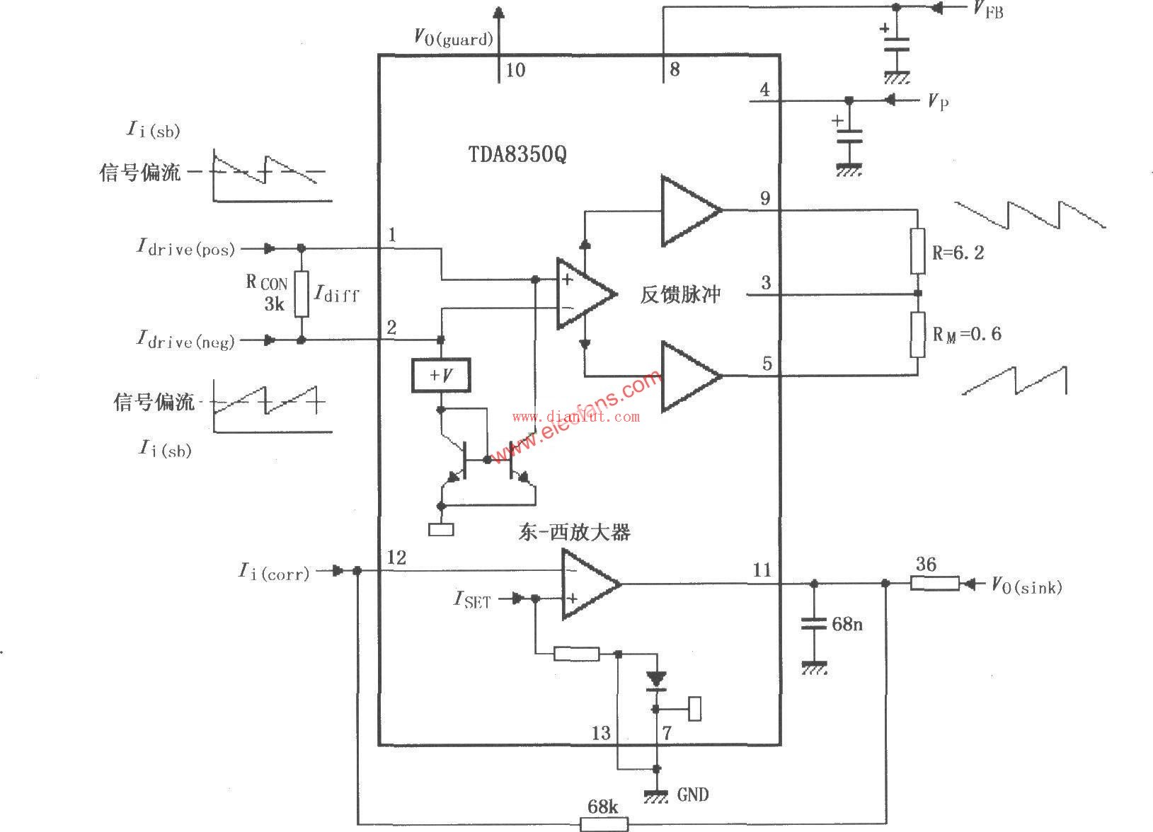
The following is the circuit diagram of the TDA8350Q Application Circuit. This schematic provides a clear view of how the TDA8350Q chip is integrated into a typical system setup.
During testing, the output of the push-pull power amplifier was connected to a resistor as a dummy load instead of using a deflection yoke. This method helps simulate real-world conditions while ensuring safety and accuracy during the evaluation process.
Editor: Circuit Diagram
New Energy Cable,Battery Cable,Female Socket Car Charger,Automotive Charging Plug
Dongguan City Yuanyue Electronics Co.Ltd , https://www.yyeconn.com