introduction
This article refers to the address: http://
Generally, the power supply device can only measure the overall output voltage and current of the battery pack, and online measurement cannot be performed for a single battery. The failure of the battery pack is often a vicious cycle starting from the failure of the single battery. Especially for battery packs that have been used for a long time but do not exceed the service life, it is difficult to find problems by simply relying on the maintenance of the maintenance personnel. Therefore, online monitoring of the operating parameters of a single battery makes it extremely important to find problems in time.
The damage of a single battery is first manifested in an abnormal phenomenon in which the terminal voltage is too high during charging and rapidly drops during discharge, the battery body temperature rises, and the load capacity decreases. The faulty battery can be found in time by online measurement of the terminal voltage and body temperature of the battery.
Early battery online monitoring uses a centralized monitoring method, or a distributed measurement method based on RS-232 (or RS-485) bus for distributed acquisition and centralized monitoring. These methods can only use the master-slave system structure to collect data in a polling manner. This is because the RS-232 and RS-485 buses are just a pure physical interface and do not have active coordination capabilities. CAN bus is a multi-master control LAN standard, with network layer of physical layer and data link layer, multi-master node, non-destructive arbitration, high reliability and good expansion performance. A distributed battery online monitoring system based on CAN bus is given below.
System composition
The system consists of the host computer, RS-232-CAN interface and intelligent node, as shown in Figure 1.
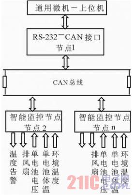
Figure 1 Schematic diagram of distributed battery online monitoring system
The upper computer is composed of an ordinary microcomputer, receives the monitoring data of each node, establishes a battery operation database, processes the collected battery data (such as recording the battery history, collecting data, etc.) and outputs the display in a table or graphic manner. , manage the operation of the entire system, and so on.
The RS-232-CAN interface is the interface between the CAN bus and the host computer. It completes the data conversion between the CAN bus data and the RS-232 interface, buffers the data information from the intelligent node, and alerts the alarm signal to notify the maintenance personnel to process.
The intelligent node is an intelligent monitoring module that measures the voltage, body temperature and ambient temperature of a single battery in a battery pack (total voltage 48V, monolithic voltage 12V or 2V). If the working range is exceeded, an alarm is generated, and the monitoring data is stored, and the monitoring data is periodically reported. The over-limit alarm signal is reported in time and can be polled by the host computer. The detailed design scheme is given below only for the intelligent node.
Hardware composition
The intelligent monitoring node uses 89C52 as the controller, and the peripheral modules include CAN interface module, temperature measurement module, voltage measurement module, alarm module, node address selection and optional memory module, as shown in Figure 2. In order to make full use of the 89C52 interface resources, all modules except the CAN interface module use serial interface devices, which reduces the circuit size and reduces the hardware cost of the circuit.
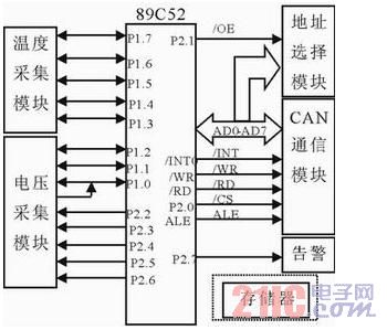
Figure 2 intelligent monitoring node structure
CAN interface module
The CAN bus protocol and its characteristics can be found in the references. At present, there are many chips with CAN protocol function. This design uses the common PHLIPLE company's SJA1000 independent CAN controller chip and 82C250 CAN interface driver chip. In order to enhance the anti-jamming capability of the node, TX0 and RX0 of SJA1000 are connected to 82C250 through high-speed optocoupler 6N137. The circuit is shown in Figure 3.
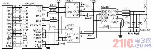
Figure 3 Schematic diagram of CAN interface module
Voltage measurement module
When the battery is made up of 4 12V batteries, the voltage at the line terminal is much higher than the allowable input voltage of the ADC. Therefore, the voltage acquisition circuit should be specially designed: the battery terminals of the battery packs in series will be connected. The analog switch is respectively introduced into the voltage dividing circuit for voltage division processing, and then subjected to impedance conversion by the voltage follower, and then sent to the differential input end of the ADC, and the converted voltage digital quantity is output to the PI port of the single chip microcomputer.
The ADC uses ADC0838 from National Semiconductor. The device is an input programmable, single-ended 8-channel/differential 4-channel, 8-bit serial ADC with data input and output ports that can be shared time-sharing.
The analog switch uses the MAX4613 from MAXIM. It is a four-way single-pole single-throw TTL/CMOS compatible analog switch that can be powered from single-ended (9~40V) or dual-ended (±4.5~±20V). The connection to the battery pack is “floatingâ€. Each MAX4613 controls the strobe of two batteries. The power and ground take the positive and negative poles of the two batteries in series. Since the control polarity of S1, S4, S2, and S3 of the MAX4613 is reversed, the decoding circuit cannot be used, but the four I of the microcontroller.
The /O line is separately driven by the optocoupler to ensure that only one battery voltage is connected to the voltage divider circuit of the latter stage. In addition, its control terminal uses CMOS level (VL to V+).
The voltage dividing circuit uses three identical resistors, and the voltage after voltage division is about 4V. Due to the use of the same voltage divider network, errors between the various paths due to differences in the voltage divider network are avoided. Simultaneous analog converters use differential inputs to reduce common-mode interference and avoid voltage incompatibilities caused by “floatingâ€. If you sample 2V battery, you can use 6 CD4052 analog switches to control the strobe of each battery. Each CD4052 controls 4 batteries. The two I/O lines are separated by optocoupler to drive two address selection terminals. The three I/O lines are decoded by 74LS138 to control the enable terminals (INH) of the six CD4052.
Temperature measurement module
The temperature measurement module uses the DS18S20 series single-bus digital thermometer introduced by DALLAS in the United States. Only one wire can be used to connect the MCU to the DS18S20, as shown in Figure 4. Each I/O line can be connected to multiple DS18S20s at the same time.
Software implementation
The software design adopts modular programming. The system software is mainly divided into main program, data acquisition (voltage, temperature) processing program and communication program.
The main program is a system control program, which realizes initialization of the system (including system self-test, reading the address of the node, battery type of battery pack, sending the address of the node to the host computer, and receiving the reference voltage value of the node sent by the host computer. And temperature values) and the overall scheduling of each module software.
Data acquisition processing procedures include voltage acquisition and temperature acquisition. Since the temperature conversion time of the DS18S20 is long (750ms), the temperature conversion and voltage acquisition are performed first for each acquisition, and then the temperature is collected. Temperature conversion and voltage acquisition are performed simultaneously. After each round of collection, the data should be processed to determine whether the limit value is exceeded. If it is normal, it is judged whether it has been collected 5 times, and if not, it is collected again. This is because the data conversion is slow. If it is normal, there is no need to report the data every time to reduce the amount of data on the CAN bus. If it is 5 times or the data is out of limits, the data is packaged and uploaded, and the CAN communication phase is entered. .
The CAN communication program is responsible for transmitting the collected data to the CAN controller, which in turn is responsible for transmitting the data to the CAN bus. The main subroutines are: CAN initialization, CAN transmission, CAN reception, ADC subroutine, DS1820 reset, start, ROM search, read and write. Among them CAN initialization, transmission and reception subroutine, DS1820 reset, start, ROM search, read and write, etc. can refer to the following references, ADC conversion subroutine details see the website of this journal.
Conclusion
The distributed battery intelligent monitoring system has high intelligence, accurate measurement, and can detect early faults in the battery pack in time. The intelligent monitoring node can be used as a component of distributed acquisition and centralized monitoring of multiple sets of batteries of one station, or can be used as a subsidiary part of the switching power supply. The CAN interface can be replaced by an RS-232 interface to connect with the control host of the existing switching power supply to improve the performance of the existing power supply.
Heavy weight belting products are available in multiple widths and styles. Most of the heavy weight fabrics are heavily coated with PTFE to ensure consistent and reliable release performance. Besides that, its outstanding performance in wear resistance, coefficient of friction and compression strength make it suitable for diverse applications as polymer casting, lamination, composite manufacturing, rubber curing.

PTFE Conveyor Belts,Fiberglass Conveyor Belt,Non Stick Conveyor Belts,PTFE Coated Conveyor Belt
TAIZHOU YAXING PLASTIC INDUSTRY CO., LTD , https://www.yaxingptfe.com