Along with the continuous development of urban transportation technology, people enjoy the efficient and convenient way of highways, and the traffic accident rate caused by them is also increasing. The proportion caused by the pressure of tires is as high as 80%. This phenomenon makes people want to The tire pressure during driving is monitored. Some developed countries have introduced relevant regulations (the US TREAD regulations), requiring new electronic vehicles to be equipped with safety electronics that can monitor the tire pressure in motion. Therefore, the installation of tire pressure monitoring system (TPMS) in the future car will also be the same as ABS and airbags, which is an inevitable development trend. The tire pressure monitoring system monitors the pressure in the tires around the clock, and alarms the leakage and low pressure and high pressure of the tires, so that the vehicle is always in safe operation.
This article refers to the address: http://
1 system design
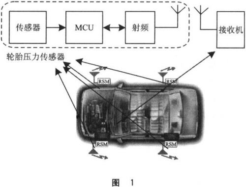
The TPMS system consists of a tire pressure sensor and a receiver. The tire pressure sensor uses MicrochiP's PICl6F628A low-power 8-bit MCU, the pressure sensor uses Infineon's SPl2, and the RF IC uses N0rdic's nRF40l.
The pressure sensor installed in the tire transmits the pressure and temperature information in the tire to the receiver in the cab, so that the driver can know the pressure in the tire at any time, as shown in Figure 1.
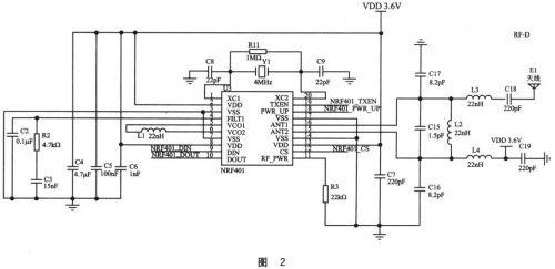
1.1 RF circuit
In the RF signal circuit shown in Figure 2, the Norwegian Nordic, the company's nRF40l device, is a single-chip UHF radio transceiver IC in the 433 MHz ISM band. It uses FSK's modulation and demodulation technology, its maximum working speed is up to 20 kb, and the transmit power is adjustable up to 10 dBm. The basic technical indicators are as follows:
The central carrier frequency point is 433.92/434.23 MHz;
Maximum transmit power is 10 dBm
The working voltage is 2.7~5.25V;
The current consumption during reception is 250μA, the maximum emission is 28 mA, and the standby current is 8/μA.
The ANT1 and ANT2 of the NRF401 are the input/output multiplexing pins of the antenna. In the input mode, the RF signal is demodulated by connecting the pin to the low noise amplifier; likewise, in the output mode, the modulated signal is output through the pin after power amplification.
Pin 4 is the input of the PLL phase-locked loop filter of nRF401. The voltage of this pin is l.lV0.2V during normal operation.
Pins 5 and 6 are peripheral circuits controlled by a piezoelectric crystal. These two legs are indirectly a 22μH inductor with a value of Q>45@433 MHz.
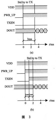
Pins 7 and 8 are data input pins and output pins, respectively. The transmission and reception of information is completed in conjunction with the potential timing on the 18-pin PWR_UP and the 19-pin TXEN. Figure 3 is a timing diagram for controlling the operation of each pin during data transmission and reception.
11-pin external RF power control resistor. As shown by R3 in Fig. 2, the value is between 22 and 100 kΩ. It generally reaches 7 dBm at around 30kΩ.
1.2 Structure of the helical antenna
Since the antennas are of different types, they should be selected according to the specific application requirements. In this application, the antenna is located in the car hub. Close to the valve. At high speeds, the antenna constantly changes direction. In order to maximize the angle of reception, a helical antenna is used.
The number of turns (N), diameter (D) and pitch (S) of the helical antenna determine the gain and directivity of the antenna.
The total length of the antenna is LN=NLO=Nsqit(S2+C2) where C=xD is the circumference of the spiral, and Lo=sqrt(S2+C2) is the length of one turn of the wire.
Another important parameter is the helix angle α, which is the angle between the tangent of the helix and the vertical plane of the helix axis. The helix angle is defined as an α=tan-1 (S/C) helical antenna having the following two modes of operation.
1 Normal mode. In the normal mode of operation, the antenna radiation field has a maximum value relative to the normal plane of the helix axis. For this mode: NLo<<λ.
2 axial (endfire) mode. This mode of operation has only one main lobe, its maximum radiant intensity is along the helical axis, and there is an oblique angle between the secondary and the shaft. To excite this mode, its diameter D and space 3 must be a large fraction of the wavelength.
1.3 sensor circuit
SPl2 is the tire pressure sensor IC of Infineon. As shown in Figure 4, the pressure and temperature, acceleration and voltage detection circuits are integrated by MEMS technology, and the indication values ​​of each physical quantity are directly output in digital form, and the SPI protocol is adopted with the periphery. Interact.
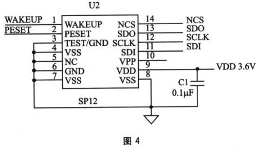
At the same time there are two internal clock signals, WAKEUP and RESET. WAKEUP outputs a pulse signal every 6s, RESET outputs a pulse signal every about 54min, and the low electron is valid.
1.4 System Power Consumption
Since the overall quiescent current of the TPMS system is required to be less than 20μA, it is guaranteed that the selected device must be a low-power or ultra-low-power chip. The quiescent current of PICl6F628A is 0.1 μA, the quiescent current of sensor SPl2 is 0.6 μA, and the standby current of RF NRF401 is 8 μA.
After the actual measurement, the static power consumption Ist=Ist_mcu+Ist_sensor+ist_rf+Ist_cap=15μA. Ist_cap is the leakage current of the tantalum capacitor. Dynamic power consumption is 25 mA (maximum) when the RF is in continuous transmission.
2 software design
2.1 Overall design of the software
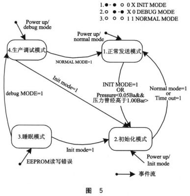
The software is generally divided into four operating modes: debug mode (for factory diagnostics), initialization mode, sleep mode (sleep), and measurement mode.
(1) Debug mode
Mainly perform some internal testing and diagnostic functions of the product. The body includes two parts: sensor test and RF test.
(2) Initialization mode
Receive the ID code and level decision threshold given by the host.
(3) Sleep mode
Operates at the lowest power consumption and responds to system operating requirements.
(4) Measurement mode
The measurement mode mainly performs the following functions:
1 Timing measurement of tire pressure and temperature;
2 When the pressure has an alarm in different levels, the same level is only reported once;
3 There is no change in pressure, and the pressure and temperature are reported once in a fixed interval period;
4 to ensure system reliability. The system is reset every 1 hour.
5 When different levels of alarms occur at the same time, the alarms are given priority at high temperature, high pressure and low voltage levels.
Their mutual conversion relationship is shown in Figure 5.
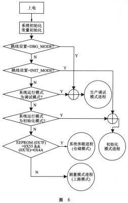
The working flow chart of the system power-on reset is shown in Figure 6.
2.2 Processing of sensor data
The SP12 is a pressure-sensing IC. The digital quantity obtained directly by the internal processing can be obtained by sending the corresponding command words and commands to the SPI physical interface, and the current tire pressure, temperature, and acceleration values ​​can be obtained. Since the PICl6F628A has no SPI module, the SPI driver can be simulated by software here. Achieve the purpose of communicating with SP12.
2.3 Processing of RF data
In order to ensure the reliability of sending and receiving data in a harsh environment, and according to the small amount of information and simple data of the application, information redundancy is adopted to ensure reliable reception of data, that is, information of the same content is continuously transmitted.
The data is sent using the USART module inside the MCU.
The data frame format is preamble + sync character + ID code + pressure + temperature + alarm bit + check code.
Data receiving processing, nRF40l in the receiving mode, DOUT pin has a continuous random signal input, how to efficiently filter out the transmitted information in the byte stream? Here, because the transmission format is fixed, it is used in the interrupt processing It is handled by means of a finite state machine.
Conclusion
The TPMS system has the characteristics of small size, low cost, and two-way gold, and is widely used. For domestic tens of millions of cars, there will be a very broad market prospect. This will set off a new wave of automotive pressure sensor applications.
The PLC splitter is used to separate or combine optical signals. A PLC is a micro-optical component based on planar lightwave circuit technology and provides a low-cost light distribution solution with the small form factor and high reliability.
Rackmount Splitter is manufactured using silica glass waveguide circuits that are aligned with a v-groove fiber array chip that uses ribbon fiber. Once everything is aligned and bonded, it is then packaged inside a miniature housing. PLC splitter has high-quality performance, such as low insertion loss, low PDL, high return loss, etc.
Advantages
Suitable for multiple operating wavelengths (1260nm – 1650nm); unstinted.
Equal splitter ratios for all branches.
Compact configuration; smaller size; small occupation space.
Good stability across all ratios.
High quality; low failure rate.


Rackmount Splitter,Fiber Optical Splitter Rackmount,1U Rack Mount PLC Splitter,PLC Fiber Optical Splitter
Sijee Optical Communication Technology Co.,Ltd , https://www.sijee-optical.com