The rising star in digital electronic circuits is digital logic. It is called a digital circuit because it is also a pulse, but these pulses are used to represent binary digits, such as high level for "1" and low level for "0". Information such as sound image text is digitized into a series of electrical pulses, which are called digital signals. A circuit that can process digital signals is called a digital circuit.
This circuit is also called a logic circuit at the same time, because "1" and "0" in the circuit also have logical meanings. For example, logic "1" and logic "0" can indicate the circuit's on and off, events, respectively. Yes and no, true and false of logical reasoning, and so on. There is a logical relationship between the output of the circuit and the input. In addition to binary arithmetic operations, this circuit can perform logical operations and logical reasoning, so it is called a logic circuit.
Digital logic circuits are widely used in computers, automatic control, communication, measurement, etc. because of their ease of integration, high transmission quality, and computational and logical reasoning capabilities. In general household electrical appliances, such as timers, alarms, controllers, electronic watches, electronic toys, etc., digital logic circuits are used.
The first feature of digital logic circuits is to highlight the words "logic" using unique graphical symbols. There are two kinds of basic unit circuits, such as gate circuit and flip-flop, which are composed of transistors and resistors. However, in logic circuits, we only use a few simplified graphic symbols to represent them, instead of drawing Their specific circuits, regardless of how high voltage they use, are TTL circuits or CMOS circuits. The diagram drawn by combining these graphical symbols according to the logic function is a logic circuit diagram, which is completely different from the general amplification oscillation or pulse circuit diagram.
The information in the digital circuit is contained in the combination of numbers 0 and 1, so as long as the circuit can clearly distinguish between 0 and 1, the combination of 0 and 1 is not destroyed, we do not care about the quality of the pulse waveform. So the second characteristic of digital logic circuits is that we mainly care about what logic functions it can perform, and less on the performance of its electrical parameters. For this reason, some special expression methods such as truth tables, characteristic equations, etc. are used in digital logic circuits, and some special analysis tools such as logic algebra, Karnaugh map, etc. are used, which are also different from the amplification oscillator circuit. .
Gate circuit and trigger
(1) Gate circuit
The gate can be seen as the simplest component of a digital logic circuit. There are currently a large number of integrated products available.
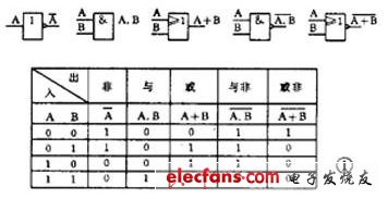
There are three basic types of gates: non-gates, AND gates, and OR gates. The NOT gate is the inverter, which turns the input 0 signal into 1 and 1 into 0. This logic function is called "not". If the input is A, the output is written as P=A. The AND gate has more than 2 inputs. Its function is that when the input is 1, the output is 1. This function is also called logical multiplication. If the input is A and B, the output is written as P=A·B. The OR gate also has more than 2 inputs. Its function is that when the input has a 1, the output is 1. This function is also called logical addition, and the output is written as P=A + B.
By combining these three basic gate circuits, various composite gate circuits can be obtained, such as a gated NAND gate, or a gated NAND gate. Figure 1 is their graphical symbol and truth table. There are also NAND gates, XOR gates and so on.
Digital integrated circuits are available in TTL, HTL, CMOS, etc., and the power supply voltages and polarities used are different, but the same logic symbols are used as long as they have the same logic function. And generally, the high level is 1 and the low level is 0.
-
High light transmittance, uniform mixing effect.
- High performance LED chip of international class brand.
- Multi - layer protection ensures a more reliable waterproof performance of lamps.
- Simple support installation for a wider installation environment.
- Aluminum alloy bottom structure, surface oxidation treatment, polymer resin package, PC outer cover, use safer;It's more waterproof and durable.The appearance is smooth and beautiful.

Led Clearance Light,Led Clearance Lights,Led Clearance Light Bulbs,Led Clearance Light Bar
Jiangsu chengxu Electric Group Co., Ltd , http://www.chengxulighting.com