Abstract: The safety of cars during driving is an important issue in daily life, and the damage caused by skidding is very large. A vehicle side slip detection device based on ATmega16 is proposed. This system introduces the ATmega16 microcontroller as the core, as well as the positive and negative power supply stability voltage, sensor signal voltage rise, digital tube control and some alarm prompt circuits. A side slip detecting device with an error of no more than 0.1 in the detection of the vehicle side slip is realized. After the test in the workshop, the error of the system still does not exceed 0.1, which can meet the requirements of industrial production.
Key words: ATmega16 single chip microcomputer; vehicle side slip detection; positive and negative power supply; voltage rise
With the development of the automotive industry, automobiles have a great impact on people's lives and work. At the same time, the safety issues in the use of automobiles have become a part of our daily life. Among them, the side slip of a car refers to the lateral movement of the wheel of one axle or the wheel of two axles. Such a situation is very dangerous, so it needs to be detected for adjustment. To this end, we have realized the acquisition of the sensor data of the side slide, and the voltage transmitted from the sensor is adjusted from ±2.5 V to 0~5 V through the op amp circuit, and the AD conversion is built in the ATmega16.
Finally, the data is analyzed by AVR microcontroller ATmega16 to realize the detection of the amount of vehicle side slip.
1 The composition and basic principle of the detection device The device is mainly composed of the automobile side sliding test bench, the displacement sensor, the AVR MCU and the display module. The connection mode is shown in Figure 1.
This article refers to the address: http://
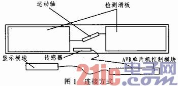
When detecting the side slip of the car, the front wheel of the car passes on the detecting slide of the sliding test stand of the car, and the detecting slide moves inward or outward during the running of the car. This amount of movement is due to the side slip of the car. We can pass the magnitude of the movement through the displacement sensor, and the data can be displayed after processing by the ATmega16 microcontroller. The width of the detecting slide plate is 1 M, and the displacement amount of the sliding plate is mm. Through the processing of the single chip microcomputer, the side slip amount of the automobile can be converted into a unit value of M/kM for display. If the absolute value of the result of the vehicle side slip is greater than 5 M/kM, it is unqualified, otherwise it is qualified.
2 AVR microcontroller control module design The entire control module includes sensor power supply module, sensor signal voltage rise module and digital tube display control module. Each module has its own specific features.
2.1 Sensor Power Supply Module The most important part of the sensor is composed of a bridge of circuits. The output is related to the voltage applied to both sides of the bridge and a variable resistor. The variable resistor is determined after the sensor is determined, and there is no way to change it. The voltage is added to the sensor through the control box. In order to make the output voltage of the sensor relatively stable, the sensor power supply module needs to be designed accordingly, so that the power supply voltage is more stable. Its working principle is shown as in Fig. 2.
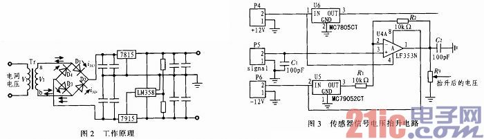
After the voltage given by the switching power supply passes through the rectifier bridge, it is filtered by magnitude and then connected to the inputs of 7815 and 7915. The capacitor function of 0.1μF in the latter stage is to remove the AC component by the principle of charge and discharge. The outputs of the 7815 and 7915 are divided by two 33 k high-precision resistors and connected to the inverting input of the amplifier LM358. The non-inverting input of the LM358 is grounded, and the output of the amplifier LM358 is connected to the common terminal of the 7915. R17 and R18 are high-precision resistors. The output terminals of 7815 and 7915 are filtered by two 47 μF/25 V electrolytic capacitors, and the AC components are filtered out by one or two 0.1 pF filter capacitors. For the composition, the output is stable with DC +15 V and -15 V. It can be applied to the excitation end of the sensor to make the sensor's output more stable.
2.2 Sensor signal voltage rise module The voltage value of the sensor used in this side slide test bench ranges from -2.5 to 2.5 V, while the built-in AD of Atmega16 can collect 0 to 5 V, so it is required. Raise this voltage value so that the correct voltage value can be collected. The voltage rise circuit is shown in Figure 3.
When the voltage is raised by the op amp, the voltage at both ends is generated by 7805, 7905. Therefore, the voltage is relatively stable, so the voltage after the rise is relatively stable, and the relationship between the input and output voltages is: 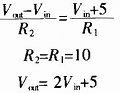
It can be seen that the adjusted voltage is twice the original voltage plus 5 V, that is, the original voltage is -2.5 to 2.5 V, and the adjusted voltage is 0 to 10 V, and the change is linear. Then, the voltage is adjusted by the potentiometer to make it conform to the 0~5 V standard, and it is linearly related, so that the raised voltage can be directly connected to the AD conversion port, and the AVR can be made by AD conversion. The MCU obtains the data of the current displacement, thereby achieving the purpose of detection.
2.3 The digital tube display control module controls the digital tube, and needs to control the position selection and segment selection of the digital tube separately, that is, two signals are needed for control. At the same time, the output voltage of ATmega16 is 5 V, and the voltage of the digital tube should be about 1.8 V. Therefore, a latch should be connected between the output of the MCU and the digital tube, that is, the voltage can be reduced, and Some signals are latched so that some values ​​can be displayed for a long time. The control method of the digital tube is shown in Figure 4, where P1 is the chip select control output and P2 is the bit select control output. And Figure 4 also shows the signal input.
ATmege16 and some hint signal output.
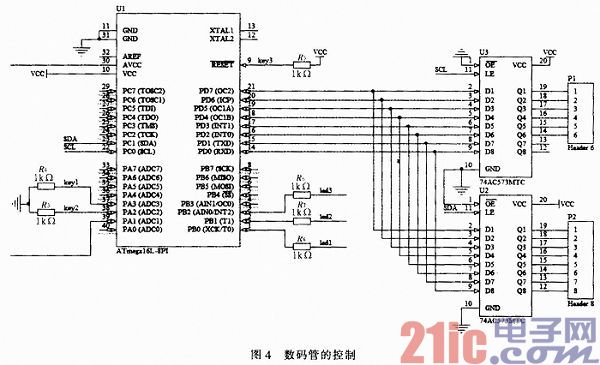
The control of the digital tube is completed by the single-chip microcomputer, and the content that needs to be displayed is cyclically refreshed by the single-chip microcomputer for each digital tube display, so that the data displayed by the digital tube can be continuous and visible. Achieve the purpose of displaying the test results.
2.4 The overall module MCU module is to connect the corresponding modules together. Then some alarms of LED lights are needed. The connection method of LED lights is also given in Figure 4. The connection between the microcontroller and the sensor provides the sensor's excitation signal to the sensor supply module. The sensor signal voltage boost module receives the sensor's signal and raises it to 0 to 5 V, which is then supplied to the ATmega16.
3 software part design The system needs software to analyze and display the results of its AD conversion, and it is necessary to collect the maximum value of the sliding plate during the driving process of the car to determine the amount of side slip of the car, and the data needs to be calculated. Displayed after the corresponding conversion. The flow chart of the software is shown in Figure 5.
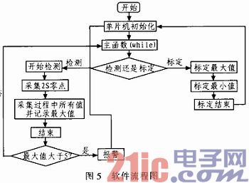
The calibration has a maximum calibration and a minimum calibration. When calibrating the maximum value, the sliding plate needs to be moved outward by 1 cm, and the corresponding voltage value of the sensor at this time is recorded by the single chip microcomputer. When calibrating the minimum value, the sliding plate needs to be moved inward by 1 cm, and the corresponding voltage value of the sensor is recorded by the single chip microcomputer. With these two values, and know that the left side of the sliding plate moves 1 cm, that is, the difference between the sliding plates of the two voltages is 2 cm. Then, according to the linear change of the voltage caused by the movement of the sensor by the sliding plate, we can determine the relationship between the moving distance of the sensor and the voltage change. In the subsequent detection, the value of the change in voltage can be used to determine the distance the sliding plate moves.
At the time of detection, the voltage of the sensor was initially collected 200 times and averaged. This value is used as the zero point voltage value of this test. After that, the acquisition is averaged 5 times in order to ensure that more data can be collected and the maximum voltage is worth. During the acquisition process, each voltage value obtained is compared with the zero voltage value, and the two points with the largest voltage difference are buffered. When the end detection is clicked, the difference between the buffered voltage value and the zero voltage value is a reflection of the result of this measurement. The relationship between the voltage and the displacement of the sliding plate can be used to obtain the maximum displacement of the sliding plate after the car passes over the sliding plate during the measurement. Finally, after the conversion of the unit, the amount of side slip of the test was obtained. The amount of side slip is displayed by a digital tube. If the amount of side slip is greater than 5 m/km or less than -5 m/km, the vehicle side slip is unqualified, and the single chip microcomputer controls the buzzer to alarm. Then return to the selection phase.
4 Test results After the design is completed and installed, the system is first calibrated and then tested. It is known that the sliding plate has a length of 1 m, that is, the final side slip amount is 1 m/km for every 1 mm of the sliding plate. Table 1 shows the test results.
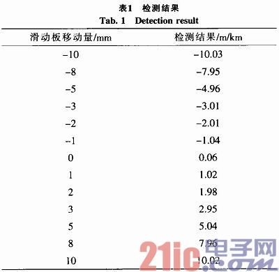
As can be seen from Table 1, the error of the detection results does not exceed 0.1. The error of the national standard for skid detection is not more than 0.2. And this data is the result of the workshop test. The noise interference in the workshop is large, but the test results are still accurate. So this system can be practical.
5 Conclusion The side slip detection system runs stably, and can accurately collect the voltage of the sensor and obtain the accurate side slip value during the measurement. And this system uses ATmega16, low power consumption, high efficiency, high integration and space saving. In the process of signal acquisition, multiple acquisition and averaging methods are used. Since the signal voltage is generally burred, the average after multiple acquisitions is likely to remove the burrs of the voltage. In addition, the best part of the system is the use of a very stable positive and negative power supply, so that the signal voltage to the sensor is also very stable. In addition, after some filtering processing of the signal voltage of the sensor, the signal voltage for processing the ATmega16 is stable, so the result is very accurate. It can also be seen from the test results that the design can be applied in practice.
Buffet Server,Household Restaurant S.S Buffet Server,Heated Buffet Server,Kitchen Buffet Server
Shaoxing Haoda Electrical Appliance Co.,Ltd , https://www.hotplates.nl