Since the early industrial revolution, people have needed to use machinery and equipment for measurement, control, and communication. Instrumentation systems using sensors and actuators have become the backbone of modern manufacturing plants. Through the transmission line, the communication method using 4 mA to 20 mA analog current signal for data transmission and setting has been widely used for a long time. But the instrument is also maturing day by day, from the early pure analog system to the currently used "smart" system, using HART (addressable remote sensor high-speed channel) protocol and other technologies to enhance the communication function. In short, the DC low frequency circuit signal is modulated by an independent higher frequency signal, and the signal is switched between a pair of frequencies (Figure 1)-this technique is called Frequency Shift Keying (FSK).
This article will introduce the implementation of the technology, and provide some application examples, discuss some of the devices used in modern silicon integrated circuit technology, to help system designers. In addition, in order to explain the technology, we will also introduce the HART modem (modulation-demodulation) IC--ADI's AD5700, which is the most compact, lowest power consumption, widest voltage range, and fully compliant with the specifications.
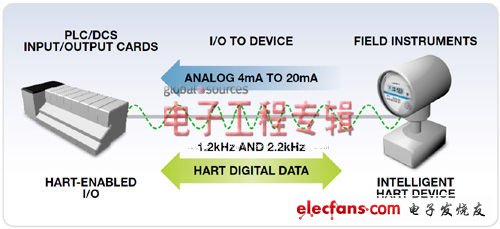
Figure 1. HART communication.
What is HART communication?
The main communication method used in the analog transmitter is the current loop. The normal range is from 4 mA to 20 mA. The transmitter, receiver, and power supply are used. It can realize many functions, such as remote calibration, fault query and process variable data transmission. Low-power transmitters and receivers must operate at a minimum current of 4 mA or less, depending on the “margin†required for error indication. These current loops are very reliable and stable, and have a very high performance in long-distance communications. Strong anti-interference ability. However, one of its major disadvantages is that the single loop only allows one-way communication (from the sensor or sent to the actuator) and can only transmit one process variable.
The introduction of the HART standard provides a way to create "smart" transmitters by adding digital communication capabilities and sharing the same twisted pair used for traditional 4 mA to 20 mA instruments. The 4 mA to 20 mA analog circuit is modulated by the 1 mA peak-to-peak FSK signal-without interrupting the original primary variable transmission, while still leaving room for loop operation. The HART protocol has become a global standard for sending and receiving digital signals through analog lines between smart devices and control or monitoring systems.
Internal structure of HART modem IC
The AD5700-1 complete HART modem IC (Figure 2) integrates all necessary filtering, signal detection, demodulation, and signal generation functions, thereby significantly reducing the number of external components required. It is packaged in a small 4 mm & TImes; 4 mm, 24-lead LFCSP and requires only a single power supply from 2 V to 5.5 to operate in the extended temperature range of –40 ° C to + 125 ° C.
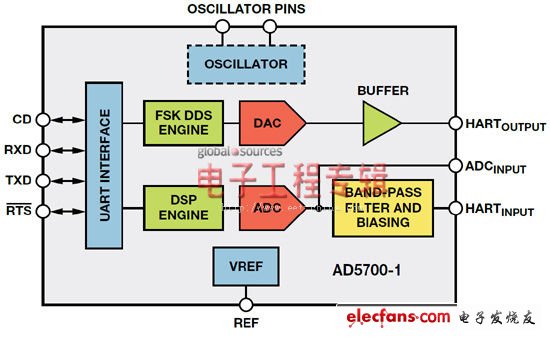
Figure 2. AD5700-1 block diagram; -1 option includes internal 0.5% precision RC oscillator.
Launch path
Figure 2 shows the main modules involved in modulation: FSK direct digital synthesis (DDS) engine, DAC (switched resistor string type) and buffer. The digital data to be sent is input through the UART. The modulator is enabled by pulling the RTS (Request To Send) signal low. The modulator converts the UART encoded HART data bit stream at the TXD input into a series of binary 1200 Hz ("1") and 2200 Hz ("0") tones (see Figure 3). DDS generates a sine digital word stream at any frequency, and the DAC converts it to a pp analog sine wave of approximately 493 mV. This sine wave signal is internally buffered and output on the HART_OUT pin. The DDS engine itself generates continuous phase signals, so it avoids any output discontinuities when switching between frequencies. The main advantage of internal buffering on HART_OUT is the high drive capability, no need for external analog buffering, and the problems they cause. The HART_OUT pin is DC biased to 0.75 V and should be capacitively coupled to the load.
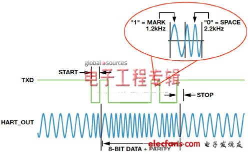
Figure 3. AD5700 / AD5700-1 modulator waveform.
Receiving path
When RTS is at a logic high level, the modulator is disabled and the demodulator is enabled, which means that the modem is in receive mode. The receiver demodulates the FSK modulated signal on the HART_IN pin. In this mode, the relevant modules are the internal bandpass filter, ADC and DSP engine. CD high level (carrier detection) indicates that a valid carrier is detected. The demodulated data is sent to the host processor through the RXD pin on the UART interface.
The purpose of our selection of the receiving architecture is to allow the AD5700 to resist noise and interference in harsh industrial environments. By using a combination of analog filtering and digital filtering, excellent sensitivity and highly accurate output can be achieved on the RXD pin. The HART bit stream was preceded by a standard UART frame, which contained a start bit, 8-bit data, a parity bit, and a stop bit. In demodulation mode, the modem has two filter configuration options: internal filter (HART signal applied to HART_IN) and external filter (filtered HART signal applied directly to ADC_IP). The external filter mode supports the use of the AD5700 in explosion-proof and intrinsically safe environments. It includes a 150 kΩ resistor, which limits the current to a sufficiently low level to comply with intrinsic safety requirements. It is recommended to use this option for the operation of safety-critical applications. The modem must be isolated from the high voltage of the loop power supply. In this case, the input terminal has a higher transient voltage protection function, so even in the most demanding industrial environment, no additional protection circuit is required.
Other modules
The other three modules shown in Figure 2 are the aforementioned UART interface, internal reference, and oscillator. RTS and TXD are important signals for modulation, while CD and RXD are very important for demodulation. The AD5700 can receive an external 2.5 V reference and can only be used when the AVDD power supply is greater than 2.7 V. The use of internal or external reference options is controlled by the polarity of the REF_SEL pin. For the clock, the device supports multiple solutions to achieve a simple, low-cost configurable solution. AD5700 can use external crystal, ceramic resonator or CMOS input. The AD5700-1 is the first HART modem IC that integrates an internal low-power 0.5% precision oscillator, reducing the required external circuits and overall cost. Numerous on-chip integration functions significantly simplify the design of HART compatible systems, thereby providing a more reliable and cost-effective stable network solution.
Examples of low-power applications
Low power consumption is very important because the power consumption of all circuits powered by the loop must be less than 3.5 mA. Figure 4 shows an example of HART communication application in the loop. On the AD5700 control board, the AD5700 HART modem interfaces with the AD5421 16-bit serial input loop-powered 4 mA to 20 mA DAC and ADuCM360 microcontroller to demonstrate the use of measuring pressure (“0â€) and temperature (“1 ") Two loop-powered transmitter circuits sharing a data channel.
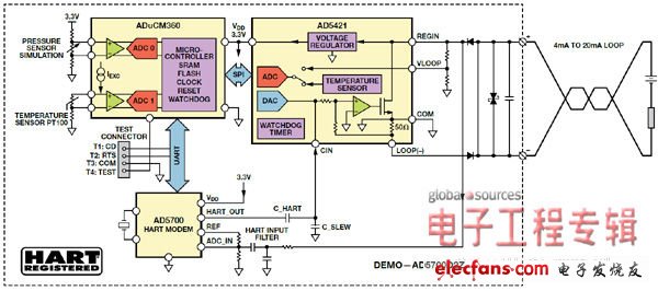
Figure 4. In HART communication, the AD5421 loop DAC and AD5700 HART modem act as loop-powered data transmitters.
The circuit has passed compatibility testing and verification and is registered as a HART solution certified by the HART Communication Foundation. Product registration details are provided on their website.
In such 4 mA to 20 mA loop-powered applications, the most important limitation is that the power consumption of the entire circuit must be less than 3.5 mA ("low limit alarm" setting, which is 0.5 mA lower than the lower signal limit of 4 mA). In such applications, the low-power specifications of the AD5700 are extremely important. In terms of meeting power consumption specifications, every microampere is very important. If each IC in the design draws a sufficiently small current, it will not exceed the 3.5 mA budget, and the application will operate normally. The typical transmit and receive currents are 124 μA and 86 μA, respectively, and the corresponding maximum specified current consumption is 140 μA and 115 μA, respectively. The AD5700 does not have a significant impact on the overall current budget.
in conclusion
In addition to the industry's lowest power consumption HART modem IC, ADI also provides complete HART solution functions, including microcontroller products, amplifiers, precision references, switches, ADCs and current-output DACAD5700 HART modems can easily interface with the following devices: AD5421, used in the application example of the loop-powered smart transmitter described above; AD5422 16-bit voltage output and current output DAC for field instruments or analog I / O cards; AD5755-116-bit four-channel DAC, using Innovative dynamic power control technology for multi-channel applications. In addition, elements that can be seamlessly matched can also be used throughout the signal chain. When used in conjunction with the AD5700 / AD5700-1, it can simplify system design and enhance reliability, enabling fast and easy deployment of stable HART-compatible systems.
Shaded Pole Ac Motor,Ac Shaded Pole Motors,Shaded Pole Motor,Shaded Pole Induction Motor
Changzhou Sherry International Trading Co., Ltd. , https://www.sherry-motor.com