introduction
This article refers to the address: http://
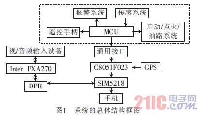
With the mature development of the third generation mobile communication network, the application of video surveillance technology based on mobile communication networks is more and more widely used. Based on the advantages of high coverage, high reliability and fast transmission rate, this paper designs and implements visual monitoring of automobile anti-theft alarm system. Based on the existing electronic car burglar alarm, this design realizes the function expansion of the original alarm system of the car body by extending the general interface. The overall structural block diagram is shown in Figure 1. This paper focuses on the design and implementation of the video surveillance part of the system.
The video monitoring part of the system is based on the hardware platform of InterPXA270 as the core, and realizes the upper layer application by constructing software development of embedded WindowsCE operating system. The design develops the camera driver by means of streaming interface, and realizes the real-time image data acquisition under the embedded WindowsCE by using the interface provided by the camera driver. The original image is encoded and compressed in MPEG-4 format, and the SCEET programming is implemented on the Windows CE side. Monitor the transmission of data.
1 hardware platform
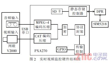
The structure of the existing automobile anti-theft alarm system is shown in the dotted line frame of Figure 1. This paper focuses on the design and implementation of the video monitoring part of this system. The hardware of the video monitoring part includes three parts, a camera that collects monitoring data, a multimedia processor, and a communication module. The hardware construction structure is shown in Figure 2. The hardware platform of the video monitoring part is based on the InterPXA270 processing chip of InterXScale microarchitecture, and the SIM5218 module is selected as the 3G communication module. The dual port RAM technology is used to realize the video processing and the overall structure of the system of Fig. 1 is the dual CPU of the 3G communication module. Communication between. Among them, the InterPXA270 chip's main frequency is 520Hz, and the WirelssMMX technology is added at the same time, which greatly improves the multimedia processing capability. In addition, PXA270's InterSpeedStep dynamic power management technology reduces the power consumption of the device while ensuring CPU performance. Siemens' 3G communication module SIM5218 supports data transfer rates up to 7.2Mb/s and provides UART, USB2.0, GPIO. And the rich peripheral interface such as I2C reduces the design difficulty; in this design, the camera selects the mesh 2000, which uses the OV511 chip as the core, has COMS 3 megapixel resolution, and uses USB communication, which can adopt the flow interface method in real time. Collect monitoring data.
2 software features
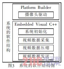
The software architecture based on the Windows CE operating system consists of two parts.
Using PlatformBuilder to customize WindowsCE system and develop USB camera driver and data sender development, this article details the design of USB camera driver and the program design of the sender. The software structure of the system is shown in Figure 3.
The Windows CE stream interface driver is a driver with a custom interface, represented by a dynamic link library DLL at the user level, which is a generic type of device driver. The functions used to implement a fixed set of functions in a stream interface driver are called stream interface functions. These stream interface functions allow applications to access these drivers through the file system. The stream interface driver supports almost any type of external device that can be connected to a Windows CE.net-based platform, including USB devices.
The main task of the stream interface driver is to pass the use of the peripheral to the application, which is implemented by representing the device as a special file of the file system. The application calls the stream interface function through the API function of the file system, and then the stream interface driver calls the native driver or interacts with the system kernel or peripheral through the device manager.
2.1 Implementation of the stream interface function of the camera driver
Developing a camera driver involves a set of standard stream interface driver functions, such as CAM_Init(), CAM_Deinit(), CAM_Open(), CAM_Read(), etc. These functions are the interface driver's DLL interface, where CAM_Init(), CAM_Open(), CAM_Read(), and CAM_IOControl() are the most important. These important functions are described in detail below.
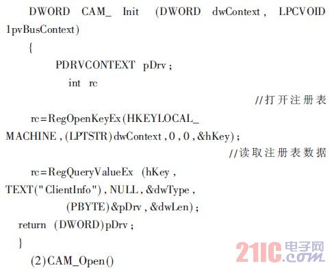
(1) CAM_Init()
The CAM_Init() function is called by the ActiveDeviceEx() function provided by the device manager. When the device is initialized, the device handle information is written to DriversActive through ActiveDeviceEx(). When the application is initialized, the address of the registry will be passed to CAM_Init() as the Context parameter, and the function will be opened by using RegOpenKeyEx(), RegQueryValueEx() and other functions. And read and write registry operations, etc. After the execution is successful, return the handle information of the USB device. Part of the source code for the driver:
(2) CAM_Open()
Before reading the device, first call CAM_Open() to open the device by executing CeratFile(). The first parameter required by CAM_Open() is the device handle returned by CAM_Init() when the application is initialized. Then set the device shutdown event to no signal state.
The following is part of the source code:
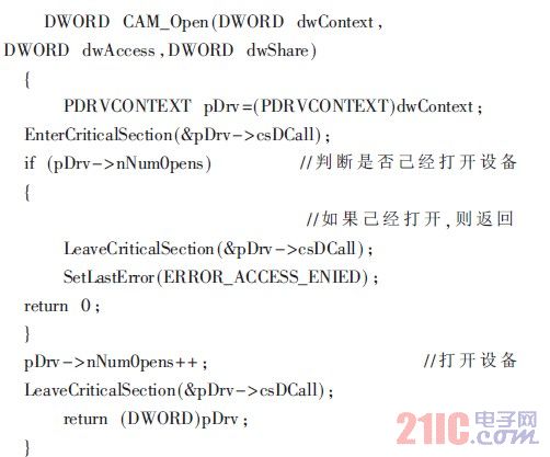
The functions of the EnterCriticalSection() and LeaveCriticalSection() functions involved in the program are to ensure that all accessed resources in the critical section are not accessed by other threads until the current thread executes the critical section code. EnterCriticalSection() and LeaveCriticalSection() are represented as entering the critical section and exiting the critical section, respectively.
(3) CAM_IOControl()
In the program design, the CAM_Open() function is used to open the camera device through the CreatFile() function, and the return value is passed to the CAM_IOControl() stream interface function through ReadFile(), and CAM_IOControl() calls OV51xReadOneFrame() to read the USB device data. The following is part of the source code:

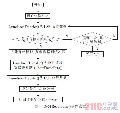
For data transmission on the USB bus, there are four types of transmission, namely control transmission, interrupt transmission, bulk transmission and real-time transmission. These four transmission types are respectively applied to different USB devices. The real-time transmission is suitable for transmission at a fixed rate or a specific time, and can tolerate occasional erroneous streaming data. For a USB camera, such a device with high real-time requirements generally uses real-time transmission, so it needs to be used in CAM_Read(). The real-time transfer function IssueIsochTransfer() reads the data collected by the camera. If IssIsochTransfer() returns a flag handler after execution, it means the execution is successful. If there is no return value, it means the execution fails.
Each time a packet of data is obtained, the frame start tag is looked up, and if found, all remaining data is copied into the application's buffer. In the Ov51xReadOneFrame() function of the program, pDataBuff applies 9610B space, and dwFrameLen is the length of each transmission 10 times, which is set to 961 here. Figure 4 is a flow chart of the Ov51ReadFrame() software.
2.2 Design and implementation of communication sender
The communication sender mainly completes RTP/RTCP protocol encapsulation and decapsulation, network transmission and data acquisition. This paper implements MPEG-4 real-time streaming media transmission based on RTP/UDP/IP protocol stack, which is a sub-module of network transmission part in mobile video surveillance system. Real-time transmission of RTP is implemented using the JRTPLIB library function. The system architecture of the transmission part is shown in Figure 5.

The main function of the transmitting end is to encapsulate the audio and video stream into the RTP packet and transmit it to the receiving end through the 3G network, and simultaneously send and receive the RTCP packet for feedback control, in order to achieve the best effect. Real-time streaming media transmission is programmed by calling the JRTPLIB function library based on the Windows CE platform.
Since the RTP protocol is not implemented as a separate network layer, it adopts the concept of application layer framing as part of the application code. This article implements RTP encapsulation grouping by an application for a specific media application, and then hands over the RTP packet. UDP interface, using JTHREAD as a thread library to complete multi-threaded operations. The use of RTP for video transmission is done in two sessions: one for voice transmission and the other for video transmission.
The main program of the sender is as follows:

3 Conclusion
Based on the existing automobile anti-theft alarm system, this paper realizes the video monitoring function based on 3G network through the expansion of the interface, and elaborates the design of the stream interface function and communication sender of the camera. In addition, through the extension of the system's universal interface, the system can also be combined with specific industry or home applications to enable mobile phones to visually monitor small areas. The design and implementation of the system not only has important significance for the development of automobile anti-theft products, but also provides a good application prospect for the development of visual monitoring based on 3G networks.
A Patch Cord is a fiber optic cable used to attach one device to another for signal routing. Normally, ST stands for Straight Tip- a quick release bayonet style connector. ST connectors are cylindrical with twist lock coupling. They are push-in and twist types. ST Fiber Optic Jumper is available in both single-mode and multimode versions. Both single-mode and multimode versions ST fiber patch come with a zirconia ceramic ferrule with pre-polished PC profile and convex spherical end. These end face types allow for faster polishing, and low back reflection and optical loss, while ensuring maximum repeatability
Fiber Optic Jumper,Fiber Optic Patch Cables,ST Fiber Cable,ST Fiber Patch Cable
Chengdu Xinruixin Optical Communication Technology Co.,Ltd , https://www.xrxoptics.com