Reference Design of Class D, 2.1 Channel Audio Amplifier for MP3 Player Dock
Abstract: This reference design introduces the application of the MAX9736 Class D audio amplifier in a stereo docking station. The MAX9736 2.1-channel demo box is a complete speaker docking station that uses two MAX9736 ICs to drive a three-channel speaker system consisting of two 2-inch satellite speakers and a 5-inch subwoofer. This reference design is ideal for use as the main sound source in portable audio players. The overall size of the solution is very small, and it has active equalization, power monitoring and dynamic equalization of the subwoofer.
| Designator | Qty | DescripTIon |
| C1 | 1 | 470µF ± 20% 25V aluminum electrolyTIc capacitor Panasonic® EEU-FM1E471 |
| C2, C12, C310 | 3 | 0.1µF ± 10% 50V X7R ceramic capacitor (0603) Murata® GRM188R71H104K TDK C1608X7R1H104K |
| C321 | 1 | 1µF (0603) |
| C16 | 1 | 10µF (1206) |
| C106, C109–111, C114, C206, C209–211, C214 | 10 | NS (0603) |
| C3–5 | 3 | 0.1µF ± 10% 16V X7R ceramic capacitor (0603) Murata GRM188R71C104K TDK C1608X7R1C104K |
| C13 | 1 | 0.1µF (0603) |
| C316–317 | 2 | 0.1µF (0805) |
| C303 | 1 | 0.33µF (0603) |
| C302 | 1 | 0.47µF (0603) |
| C305, C307 | 2 | 100nF (0603) |
| C103–104, C203–204, C301 | 5 | 100pF (0603) |
| C121, C220–221, C120, C314–315 | 6 | 100pF (0603) |
| C117–119, C217–219 | 6 | 10nF (0603) |
| C107, C207 | 2 | 150pF (0603) |
| C306, C308 | 2 | 15nF (0603) |
| C6–10, C15, C313, C318–320 | 10 | 1µF ± 10% 16V X7R ceramic capacitor (0603) Murata GRM188R71C105K TDK C1608X7R1C105K |
| C312, C14, C311 | 3 | 1µF (0603) |
| C216, C116 | 2 | 1µF (0805) |
| C100–101, C200–201 | 4 | 2.2µF (0805) |
| C304 | 1 | 2.2µF (0805) |
| C102, C108, C112, C115, C202, C215, C300 | 7 | 33pF (0603) |
| C208, C212 | 2 | 33pF (0603) |
| C322 | 1 | 33pF (0603) |
| C113, C213 | 2 | 4.7nF (0603) |
| C105, C205 | 2 | 68nF (0603) |
| C11, C309 | 2 | 220µF ± 20% 35V aluminum electrolyTIc capacitor (10mm x 12.5mm) Panasonic EEUFM1V221 |
| J30 | 1 | 4-pin header HIROSE DF3A-4P |
| U7 | 1 | Opto-FET (DIP6-SMT) Fairchild â„¢ H11F1SM |
| L100–101, L200–201, L300–301 | 6 | Ferrite bead (1206) |
| FB1 | 1 | Ferrite bead (1206) |
| J3 | 1 | 6-pin header |
| J10, J20 | 2 | 2-pin header HIROSE DF3A-2P |
| J2 | 1 | RCA® dual jack PCB mount |
| D1 | 1 | LED red (0603) |
| D5 | 1 | LED blue (0603) |
| Q2 | 1 | Transistor NPN (SOT23) Fairchild MMBT3904 |
| X1–2 | 2 | Connector, screw mount |
| R7 | 1 | PotenTIometer 100K SMT |
| R303 | 1 | Potentiometer 20K SMT |
| J1 | 1 | Power jack, right angle Switchcraft® 722RA |
| R1 | 1 | 10kΩ ± 5% resistor (0805) |
| R110, R210 | 2 | NS resistor (0603) |
| R111, R211 | 2 | 10.5kΩ ± 5% resistor (0603) |
| R100, R200 | 2 | 100Ω ± 5% resistor (0603) |
| R10 | 1 | 100kΩ ± 1% resistor (0603) |
| R106, R108, R206, R208 | 4 | 10kΩ ± 5% resistor (0603) |
| R300–301 | 2 | 10kΩ ± 5% resistor (0603) |
| R2–3 | 2 | 10kΩ ± 1% resistor (0603) |
| R113, R213 | 2 | 11kΩ ± 5% resistor (0603) |
| R309, R311–312, R314 | 4 | 11kΩ ± 5% resistor (0603) |
| R306 | 1 | 12kΩ ± 5% resistor (0603) |
| R114, R214 | 2 | 137kΩ ± 5% resistor (0603) |
| R305 | 1 | 14.7kΩ ± 5% resistor (0603) |
| R112, R212 | 2 | 150Ω ± 5% resistor (0603) |
| R317 | 1 | 1kΩ ± 5% resistor (0603) |
| R107, R109, R207, R209 | 4 | 1MΩ ± 5% resistor (0603) |
| R8–9, R315–316 | 4 | 2.2kΩ ± 5% resistor (0603) |
| R101–102, R201–202 | 4 | 20kΩ ± 5% resistor (0603) |
| R5 | 1 | 220Ω ± 5% resistor (0603) |
| R310, R313 | 2 | 24.3kΩ ± 5% resistor (0603) |
| R302 | 1 | 2kΩ ± 5% resistor (0603) |
| R308 | 1 | 3.24kΩ ± 5% resistor (0603) |
| R307 | 1 | 3.3kΩ ± 5% resistor (0603) |
| R115, R215 | 2 | 30.1kΩ ± 5% resistor (0603) |
| R4 | 1 | 4.22kΩ ± 1% resistor (0603) |
| R103–104, R203–204 | 4 | 40kΩ ± 5% resistor (0603) |
| R304 | 1 | 7.15kΩ ± 5% resistor (0603) |
| R105, R205 | 2 | 0Ω resistor (0603) |
| D6 | 1 | Diode, dual, common-cathode (SOT-23-3) Fairchild MMBD4148CC |
| D2–3 | 2 | Zener diode 4.3V, 20mA (SOT-23) Central CMPZ5229B |
| SPK1, SPK2 | 2 | 2in full-range loudspeaker Tymphany® 830970 |
| SPK3 | 1 | 5.25in subwoofer loudspeaker Tymphany 830945 |
| U1 | 1 | Maxim® MAX9736BETJ + (7mm x 7mm, 32-pin TQFN) |
| U2 | 1 | Maxim MAX9736AETJ + (7mm x 7mm, 32-pin TQFN) |
| U3–5 | 3 | Maxim MAX4234 (TSSOP-14) |
| U6 | 1 | Maxim MAX809_EUR-T (SOT-23) |
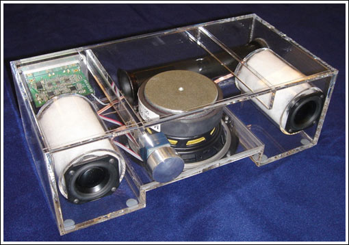
Design details The reference design is installed in a carefully designed box and contains all electronic components and speakers. The entire system requires only one external power supply and signal source.
Two 2-inch speakers are used for left and right channels, and a 5-inch speaker is used for subwoofer. One MAX9736B works in stereo mode to drive left / right channels; the other MAX9736A works in mono mode to drive subwoofer channels. The program is described in detail in two parts: the circuit part and the speaker / mechanical structure part.
Circuit Description The circuit of this reference design is divided into two parts, the left / right channel and the subwoofer channel. Each part includes three levels of circuits: input level, EQ level and power level, as shown in Figure 1.
Figure 1. MAX9736 Class D audio amplifier circuit block diagram. The design includes input stage, EQ stage, and power stage.
The input level of the left / right channel and the subwoofer channel of the input stage are the same. Stereo, log-tap potentiometers are used as volume controls to adjust the signal of the preamplifier. To avoid ground loop interference, the input stage uses a differential form, and the RCA input connector is not directly connected to the system ground. Use a 100Ω resistor to reduce the common-mode voltage; U3-A and U3-D (as shown in the schematic below) provide a gain of 2 and convert the differential signal to a single-ended output. The output of the input stage is referenced to VREF, which is the reference voltage of the power amplifier U2, which is buffered by U5-D.
After the EQ input stage, the left and right channel signals enter the two-stage parametric EQ circuit, which are located near U3-B (left channel) and U3-C (right channel), respectively. Each parametric EQ uses an op amp gyrator to simulate the inductance in the LC series resonant circuit. The series circuit has two access points, which can be attenuated or amplified, and these access points are realized by two different capacitors. For example, C105 and C106 are the first-level parametric EQ of the left channel, and are the boost and attenuation nodes of the left channel. If only C106 is used (C105 is not connected), the resonance circuit and the series resistor R105 (10kΩ) form a voltage divider to attenuate the resonance frequency signal. Conversely, if only C105 is used, the feedback is reduced and the resonance frequency signal is increased. If neither capacitor is used, the part of the circuit is disabled.
The resonance frequency f0 is calculated by the following formula: f0 = 1 / (2 × π × √ (L0 × C0)) where: L0 = R108 × C107 × R107
C0 = C105 The Q value is: Q0 = √ (L0 / (C0 × R0²)) By adding a third-stage EQ circuit to achieve tilt-type filtering, only the RC component is needed: a capacitor (C113 for boost; C114 for Attenuation) and a resistor (R111).
As a stereo Class-D amplifier IC, the MAX9736 also integrates two op amps at the input stage, which can be used as general-purpose filters. The reference design uses these op amps to build a second-order high-pass filter for the left / right channels. The operational amplifier provides inverting input and output terminals, and a multi-feedback inverting filter can be built. C116 / C216 are used to block DC input and reduce output offset.
Power stage This design provides a three-channel speaker power amplifier. The MAX9736B is used in stereo mode to drive left and right channel speakers, and can provide 2 × 11W power for 4Ω speakers. The MAX9736A is configured in mono mode for the third channel and drives the subwoofer amplifier.
In mono mode, the two Class D amplifier outputs of the MAX9736A are connected in parallel to provide greater output power. Mono subwoofer can provide 30W power (VDD = 19V) for 4Ω speakers. The input level of the subwoofer channel is the same as the input level of the left / right channel. After the input stage, the left and right channel signals are superimposed via U5-B to provide the drive for a mono subwoofer. R303 sets the gain of the subwoofer in the superposition amplifier.
In order to extend the flat frequency response characteristics to very low frequencies, the system provides a 6th order filter circuit for the subwoofer. This scheme adds a second-order active high-pass filter on the basis of the fourth-order high-pass frequency response of the open-hole speaker. U5-C provides in-phase Sallen-Key 2nd order high-pass filtering for the subwoofer.
The system requires a high Q value, with a 13dB boost at 40Hz. In order to avoid overloading of speakers and amplifiers, the Sallen-Key filter is configured to implement sliding high-pass filtering; the filter is dynamically adjusted when the amplifier output reaches the maximum value. The input resistance R305 can be automatically reduced (using optocoupler FET, U7), so that the filter Q value drops below 0.5, that is, there is no improvement.
The output peak voltage of the subwoofer amplifier U2 controls the input signal of the optocoupler FET. D6 and C16 form a peak detector, which can quickly detect the output peak voltage. The threshold of the peak detector can be adjusted or fixed, depending on whether R7 and R8 / R9 are installed. LED D5 will be turned on when the control circuit is working.
Figure 2. Simulation result of dynamic adjustment of the subwoofer channel. After the subwoofer signal reaches its threshold, the Q value of the high-pass filter decreases and the cutoff frequency increases.
The two op amps inside the MAX9736A are configured as a 4th-order subwoofer low-pass filter, which is used as a subsequent filter for the left / right channel high-pass filter.
J1 is the power input connector, used for standard laptop coaxial plug. The average output voltage of a typical notebook computer power supply is about 19V, which is suitable for the power supply of the docking station system. After filtering through C1 and C2, the voltage is marked as PVDD, and the D1 blue light is lit after the power is connected.
A simple reset circuit (U6) is used to provide a mute signal to the amplifier chip during power-up and power-down to avoid transient noise during the establishment of the input circuit signal. The mute control threshold is set at approximately 10V by R3 and R4 resistor dividers.
The MAX9736 uses patented filter-less modulation technology and does not require an external large-size inductor filter. Only simple ferrite beads (L100 and L301) are needed at the output.
The speaker and chassis subwoofer adopt Tymphany's 5-inch diameter speaker, model number is 830945, nominal impedance is 4Ω, and resonance frequency is 47.4 Hz. The left and right channels use 2-inch speakers, the model is Tymphany 830970, the nominal impedance is 4Ω, and the resonance frequency is 147.5Hz.
The f3, which is as low as 35 Hz, is designed for use in speech systems and uses a 6th-order filter circuit, including a 2nd-order high-pass active filter. The entire system is placed in a chassis, including three speakers, adjustment ports and circuit PCB. The subwoofer is installed with the opening down, which can save the size of the chassis and help improve efficiency. The chassis volume is approximately 3.79l, tuned to 54Hz. The dimensions of the chassis are approximately 355mm x 180mm x 120mm. The speaker filter equalization is designed as a 4th-order Linkwitz-Riley filter at 250 Hz; the satellite speaker equalization includes parametric EQ with f = 500 Hz, gain = +6 dB, Q = 0.5, and a tilt-type filter with f3 = 3.8 kHz and gain of +5.8 dB , Figure 3 shows the system frequency response.
Figure 3. Simulation of the frequency response characteristics of the entire system shows that the maximum flatness can be extended to 40Hz
The mechanical structure diagram given in this article originates from the prototype design, which is made of 1 / 4-inch acrylic plastic and fixed with drilling screws and acrylic glue. Consumer products may consider using more cost-effective materials, such as wooden materials, fiberboard (MDF), engineering plastics (ABS), etc.
Circuit schematic
Detailed circuit diagram (PDF, 80.4kB)
Detailed circuit diagram (PDF, 84.4kB)
Detailed circuit diagram (PDF, 92kB)
PCB layout
Detailed picture of the top silk screen layer (PDF, 277kB)
Mechanical drawing
Detailed picture (PDF, 72kB)
Detailed picture (PDF, 56kB)
Detailed picture (PDF, 52kB)
Detailed picture (PDF, 48kB)
System photos
Precautions before installation:
1.Please check the
appearance of the iPhone 8 Plus 5.5" LCD Screen carefully when receive
it to confirm whether there is appearance breakage. Any problems, Please
do not hesitate to contact us and provide photos for the problem.
2.Please
make sure you are a special repair technician, because it is not an
easy job to repair the screen (especial the flex ribbon is easy
fracture), please test the item firstly before installing it, just by
plugging the flex cable to your mainboard, we will not be responsible
for any faulty or damaged after the assembly.
3.There are
different sizes and length screws when you replace your iPhone LCD
Assembly, please remark each screw and put them in the original place.
Otherwise the screen will be easy broken if you put the screw in the
wrong place.
Test:
· On-off flex cable;
· Flash;
· Charging Port & Charging flex cable ;
· Back camera;
· Volume button;
· Mute button;
· Buzzer & Vibrator;
Features:
· 12 Months warranty.
· Flex cables are all original.
· Exquisite craftsmanship.
· Inner Package: Anti-Static Bags & Transparent Air Bubble Bags ; Outer Package: Carton Box Also In Lined With Foam;
iPhone 8/8 Plus Housing Assembly
iPhone 8 Plus Back Cover,iPhone 8 Plus Back Cover Housing,iPhone 8 Plus Housing Assembly
Shenzhen Aokal Technology Co., Ltd. , https://www.aokal.com