Transformation of Gantry Planer with Programmable Controller
1 Introduction
A plant A1024A single-arm four-meter gantry planer, its electrical system consists of the main drag and control system. The electrical main drive system is a JF-D DC speed control system, and the electrical control part adopts a relay logic control system. Since it has been in operation for more than 30 years, the electrical system has serious aging phenomena, equipment accuracy is reduced, speed regulation is poor, the failure rate is high, and the relay logic control system wiring is complicated. The number of failures and the time to deal with failures are getting longer and longer.
Therefore, using PLC to carry out CNC transformation of A1024A gantry planer to improve its processing accuracy, extend its working life, and meet customer requirements for product technical performance indicators, is a solution with less investment and quick results.
l CNC transformation plan
1.1 Requirements for the control system of the process flow of the gantry planer
1.1.1 Speed ​​regulation range
The speed range of the JF-D speed control system is 100 to 1 000 rpm / min, that is, the speed range is 10: 1; the speed range of the JF-D speed control system with grinding function is 25 to 1 000 rpm / min, That is, the speed regulation range is 40: 1.
1.1.2 Static deviation
Generally, S = 0.1 ~ 0.05, that is, S = 10% ~ 5%.
1.1.3 Automatic circular reciprocating movement of the workbench
The table should be able to reciprocate automatically during planing.
1.2 Hardware design of electric control system of gantry planer
1.2.1 The overall structure of the system
At present, the main drag part of the reformed gantry planer generally adopts a full digital DC speed control system or an AC frequency conversion speed control system, and the control part uses PLC. The full digital DC speed control system uses foreign complete equipment. The operating parameters of the equipment are displayed in English. The equipment operation and maintenance personnel need to digest and master the performance of the system. It takes a long time and has a certain technical level.
After years of promotion and use of frequency conversion speed control system, various performance and technical indicators continue to improve and mature, and the energy saving effect is remarkable. And because the various operating conditions and fault conditions of the variable frequency speed regulation system can be displayed through the monitor, therefore, according to the current development trend of electrical technology and the actual condition of the gantry planer, the principle block diagram of electrical technology transformation shown in Figure 1 is proposed.
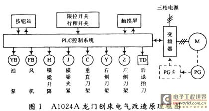
In the transformation plan, the original operation buttons are retained, so that it can adapt to the operation habits of the original operator, and most operations of the equipment can be completed by buttons. The operation instructions are transmitted to the PLC control system, and the PLC processes the instructions to control the corresponding equipment. The PLC transmits the operating status signal of the device to the button, and the button displays the corresponding information with the indicator light.
The monitor uses a touch screen, which can visually display various operating states of the entire electrical system and electrical faults that may occur in the device. Operators and electrical maintenance personnel can understand the operating status of the entire equipment and the location of the fault by viewing the touch screen.
PLC is used to realize the logic control of the switch quantity and control the direction and size of the speed of the variable frequency motor. The buttons, external stroke switch and operation handle of the button station control the oil pump, fan, beam lifting, beam clamping, vertical knife holder, right knife holder, left knife holder motor, and the backward stroke lifting knife solenoid through the PLC .
1.2.2 Design of the main circuit of the electric drive system
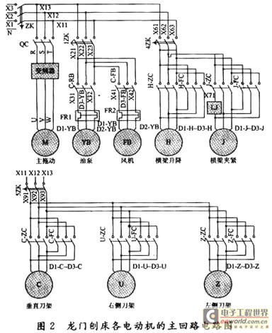
During electrical transformation, the main circuit remains basically the same, but the main DC motor is replaced by an AC variable frequency motor. The air switches 1ZK, 4ZK, 5ZK are generally in the closed state. When the equipment is running, the main air switch ZK is closed, and it is opened when it is not working. The main loop circuit is shown in Figure 2.
1.3 PLC basic unit selection and PLC external wiring diagram
1.3.1 PLC basic unit selection
According to the required input / output points of the PLC, and leave some room, choose the PLC of FX2N-80MR-001 produced by Mitsubishi. Its basic instruction execution time is 0.08μs each, the memory capacity can be expanded to 16K steps, and the maximum can be expanded to 256 I / O points. There are various analog input / output modules, high-speed counter modules, pulse output modules, and positions The control module, RS 232 / RS 422, RS 485 serial communication module, function expansion board and analog potentiometer expansion board can fully meet the design needs.
1.3.2 PLC external wiring diagram
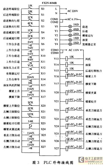
Figure 3 is the external wiring diagram of the PLC. The input part can be divided into four parts: external working environment, workbench operation, tool holder control and beam operation. The output point is divided into three parts: signal display, AC contactor coil control and inverter control.
1.4 Motor selection
The DC motor model of the original DC speed control system of the gantry planer is BCD-93. By comparison, a 55 kW 8-pole variable frequency motor is used, and its rated torque is 700.7 N · m. The torque of the 55 kW 8-pole variable frequency motor is greater than the original DC motor, which can meet the requirements of the system speed range.
1.5 Inverter selection
Through the analysis of the performance-price ratio of the products of major manufacturers, the frequency converter of Yaskawa Corporation of Japan was selected. In order to reduce the cost of transformation, Anchuan's CIMR-F7A4055 frequency converter is used. Its speed regulation range with PG V / f control mode is 1:40, and the speed control accuracy can reach ± ​​0.03%, which can meet the system speed regulation requirements.
2 Software design
2.1 Workbench control program design
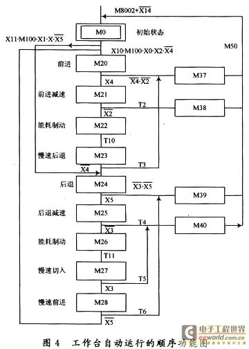
The work of the gantry planer table is divided into two modes: jog and automatic cycle. Jogging includes stepping (jog forward) and step back (jog backward), the purpose is to adjust the worktable to a suitable position in order to place the processing workpiece. The automatic reciprocating motion of the worktable is the process of processing the workpiece. The automatic cycle of the worktable is controlled by six travel switches (proximity switches) installed on the bed.
At the beginning of the automatic cycle of the worktable, the worktable is required to be between the forward deceleration travel switch X4 and the backward deceleration travel switch X5. Button to adjust the worktable to within this range. Put the oil pump transfer switch in the "ON" position. If the fan and the oil pump act, the external conditions for the automatic operation of the workbench meet the requirements. The sequence function diagram of the automatic operation of the workbench is shown in Figure 4.
2.2 Fault diagnosis program design
During the operation of the gantry planer, various faults often occur, and it is very difficult to find the faults of the old relay logic control system. After the gantry planer is controlled by PLC, the powerful information processing function and information display function of PLC and touch screen are used. When a fault occurs, the operator is notified in time through the touch screen, which can guide the maintenance personnel to deal with the fault accurately.
2.2.1 Design of fault diagnosis program for automatic operation of workbench
The automatic operation process of the table is closely related to the state changes of the forward / backward travel switch and the forward / backward deceleration travel switch. If there is a problem with these four travel switches, the workbench cannot correctly realize the automatic described in steps M20 ~ M28 Cycle process.
2.2.2 Design of fault diagnosis program for external equipment
The external equipment includes fans, oil pumps and frequency converters. When there is a failure of the external equipment, it is maintained by the start-stop circuit, and the signal is displayed on the touch screen.
3 human-machine interface design
3.1 Touch screen selection
After comprehensive consideration, the MT-510T 8-wire precision resistor network industrial touch screen produced by WEINVIEW is selected. It is a 10.4 "color TFT LCD touch screen with 640 × 480 pixels, 2 MB FLASH ROM and 4 MB DRAM. The communication port COM1 has a RS 232 port for PC and one RS 485/422 port for PLC, COM2 is RS 232 port for PLC. It also has a standard parallel printer interface.
3.2 Design of the main screen
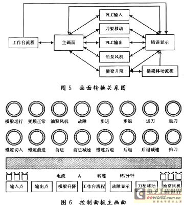
The main picture visually shows the reciprocating motion state, knife lifting action of the gantry planer worktable, and the on-off state of the limit switch related to the worktable. Use the indicator light to display the various states of the workbench, such as forward, backward, slow cut-in, forward deceleration and backward deceleration, as well as the workbench step and step back. . The indicator lamp also shows the status of the oil pump fan and inverter, as well as the feed, return and fault signals. The picture conversion relationship and the main picture are shown in Figures 5 and 6.
4 Transformation effect
The overall design of the electric control system of the gantry planer. The main drive adopts a frequency converter with a wide speed range and a significant energy saving effect. The PLC is used to realize the logic control of the switching value and the speed control of the frequency conversion motor. The control system uses a touch screen as a man-machine interface, and the touch screen uses various pictures to display the running status and fault information of the gantry planer. Practice has proved that the reformed gantry planing and milling machine greatly improves the performance and processing capacity of the machine tool, effectively improves the machining accuracy of the workpiece, and produces significant economic and social benefits.
Led Lighting,Aluminum Material Reflector,Anodized Parabolic Reflector,Parabolic Grow Light Reflector
Yangzhou Huadong Can Illuminations Mould Manufactory Co., Ltd. , https://www.light-reflectors.com