Design and Implementation of GPRS Remote Meter Reading System
0 INTRODUCTION The remote meter reading system is a comprehensive real-time information collection and analysis processing device that integrates modern digital communication technology, computer software and hardware technology, electric energy measurement technology and electric power marketing technology as the main body. The terminal uses the public mobile communication network as the main communication carrier, and realizes data communication with the system main station through a variety of communication methods. It has remote meter reading, power abnormal information alarm, power quality detection, load curve management and load control management Features.
1 System construction Each monitoring site is generally far away from the main station system. If you want to grasp the situation of multiple monitoring sites and transmit the data information of each monitoring site, such as voltage, current, power, and degree, to the main station system, you need to establish a star Type measurement and control communication network to solve the problem of remote data transmission. Because GPRS communication is a data packet communication network based on IP addresses, the computer host of the distribution center is configured with a fixed IP address, and each meter data collection point uses a GPRS module to communicate with the host.
1.1 The overall structure of the remote power monitoring system The entire monitoring system consists of a main station system and several field sites, and the site site generally includes a front-end data collector and a field subordinate computer. The system architecture is shown in Figure 1. The main work of the master station system (central manager) is to monitor and record the working status of each site, so as to achieve the purpose of remote control of the site. The on-site stations mainly collect and transmit various parameters of the electricity. The central manager can query the historical records of each on-site station, so as to achieve the purpose of scientific management of the electric power operation process and prevention of accidents. The central manager is connected to each site by GPRS. The central manager actively establishes a link, and the site receives the call and answers for data transmission. This has the advantage of avoiding simultaneous calls from multiple site sites and preventing network congestion. 
GPRS data transmission method and network structure: Through GPRS service, the device can exchange data with a server on the Internet in the standard way of Internet. The basis of GPRS is data transmission in the form of IP packets. The method for GPRS wireless terminals to access the GPRS network is similar to that of ordinary wired MODEM, and all use the establishment of PPP (Point-to-Point Protoco1) connection. PPP protocol is a widely used method for transmitting data packets on serial point-to-point links, including LCP, PAP, IPCP, NCP, etc. GPRSMODEM obtains dynamically assigned IP address through PPP protocol. After the connection is established, data communication with other computers on the Internet is realized through data transmission protocols such as TCP and UDP on the basis of the PPP protocol.
GPRS transmission method: At the remote terminal, the collected data is sent to the GSM / GPRS wireless communication control terminal through the A / D interface. The GSM / GPRS wireless communication control terminal first packs the data into a TCP / IP data packet and then converts it into a GPRS data packet. Transmit to the wireless data exchange center (MDEC) through the wireless link. MDEC strips the GPRS data packet and transmits the TCP / IP data packet to the Internet through the GGSN gateway, and then transmits the Internet to the communication control computer. The communication control computer accepts the TCP / IP data packet through the Socket socket and restores it to the original data. The situation is similar when the data goes from the monitoring center to the remote terminal.
1.2 The hardware composition of the monitoring site The design of the monitoring site is composed of a front-end data collector and a field subordinate computer. The front-end data collector is composed of a CS5460 module and an LPC932 single-chip computer. The internal of the circuit is strictly electromagnetically isolated. The digital signal formed by the measurement circuit after sampling and A / D conversion processing is then photoelectrically coupled and transmitted from the signal adapter to the slave MPC932. The I / O port can be used between the master MCU and the slave MCU Serial communication is carried out by simulating time sequence.
The on-site subordinate computer part is the core of the entire system. It is responsible for not only the communication with the front-end data collector, but also the data communication with the central manager. That is, the converted and processed signals are sent to the central manager, and they are also responsible for Communication of "clock + watchdog" circuit and display circuit. Therefore, this part of the circuit is crucial. According to the system requirements and actual application conditions, high-performance rabbit single-chip microcomputer is selected as the monitoring core of the system. Rabbit2000 is a microprocessor specially designed for embedded control, communication and Ethernet connection, with very low electromagnetic interference. Rabbit2000 is a high-performance, low-cost 8-bit microprocessor designed by Rabbit Semiconductor for an embedded environment. It is attracting attention for its C language friendly instruction set and fast digital processing functions. Rabbit2000's structure is based on Zilog's original Z80 microprocessor, but several improvements have been made: instead of using 16-bit addressing to cover storage space like the Z80 instruction set, a 20-bit or 1 megabyte actual Storage space: It is directly connected to the static memory. There are 3 memory chip selection lines and 2 groups of write / output start lines. The operating frequency of the Rabbit2000 system can reach up to 29.49MHz. Rabbit2000 on-chip peripherals include 5 8-bit parallel I / O ports, 4 serial ports, 1 sub-port, 5 8-bit timers, 1 l0-bit timer, precision pulse generation hardware, and battery-backed RTC. The serial port can use synchronous or asynchronous transmission mode, using the system frequency of 29.4912MHz, the asynchronous transmission rate can reach up to 91.6kbps.
The on-site lower-level computer mainly includes: master-slave chip MCU, display circuit, clock + watchdog circuit, GPRS and other parts. Together with the front-end data collector, it constitutes a site site. The system composition of the site site is connected as shown in Figure 2. 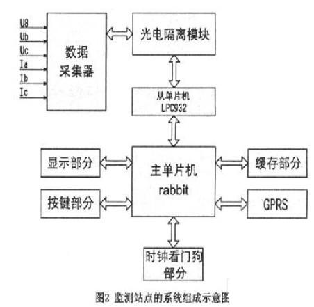
2 The overall design of the master station system The master station system consists of a personal computer plus management software. This part is composed of PC, Windows operating system, application software and database. The database uses an Access database to store the status parameters and site information of different site sites in different tables. In simple terms, the software design of this part mainly consists of the following parts:
2.1 Setting up a dynamic database A dynamic database should be set up in the computer of the management and monitoring center to store the data collected at each site, the upper / lower alarm values, and parameter setting values.
2.2 Setting various communication flags Since the communication tasks are divided into regular communication, random communication and emergency communication, by reasonably allocating various communication bit flags, the program branches according to the communication bit flags to achieve different actions.
The application software needs to be developed by itself, mainly to realize the following functions:
(1) Provide a human-machine interface for interaction with the operator. Using the Windows operation interface, the operation is simple and fast.
(2) Establish communication with the site site and exchange data.
(3) The display, storage and retrieval of data at each site, storing a large amount of historical data, can generate statistical reports, business meter readings or curves, charts and other forms according to the needs of users.
(4) The remote monitoring function is realized through the on-site single-chip microcomputer, and there are multiple setting functions at the central manager, including the selection of alarm or early warning parameters, the setting of thresholds, the call phones and mobile phones of the maintenance personnel of electrical equipment ( Or BB machine) numbers can be easily set.
(5) Add and delete system maintenance functions such as on-site sites. According to the above functional requirements, the flow shown in Figure 3 is made for the software system on the central manager side.
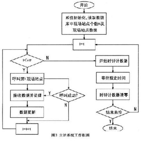
3 Working process of the monitoring system The working process of this system includes two parts, one part is the front-end data collector to collect various parameters of the electric power, and it is sent to the memory after preliminary processing; the other part is the data collection and processing of the central manager. The central manager adopts the "polling" method to dial each on-site lower-level computer for communication in turn. The lower-level computer sends the stored electrical parameters collected by the data collector to the central manager through the communication part for data processing. Get user-related data. That is, the central manager of the monitoring center sends instructions to the main chip in the lower computer through GPRS, and the parameters of the power collected by the collector include three-phase voltage UA, UB, UC, three-phase current IA, IB, IC, Active power, reactive power, power factor, etc., are sent to the slave chip LPC932 for processing, thereby transmitting data to the central manager. At the same time, once the special situation of abnormal parameters occurs, the lower computer can automatically dial the pre-stored telephone number and issue an "alarm" or prompt signal.
4 System solution Each meter uses GPRS transparent data transmission terminal, and is connected to the power distribution center through the mobile GPRS network. Electricity field service and management system is composed of database server, application server, data collection front-end machine, multi-service access platform and user field terminal system. Multi-service access platform realizes data communication in multiple communication modes, including VPN mode , PPPOE broadband network, China Mobile GPRS / GSM, 10 / l00M broadband network and various ways through the PSTN telephone network; data collection front-end machine includes data collection, terminal line failure analysis, abnormal alarm, and various abnormal information, early warning .Information is automatically submitted to 95598 customer service system, end users and system related personnel; the application server integrates various application support platforms and realizes various complex applications through business logic integration; the database system provides data storage for the application server and related various applications Provide data services.
Which has the following characteristics:
The multi-layer distributed application architecture enhances the system's extensibility. The multi-layer distribution structure lays a good foundation for the development of applications on INTERNET / INTRANET. Improve the reusability of software resources. Reduce secondary development costs.
Convenient system maintenance: After the client software is installed once, the subsequent maintenance work is only on one application server, which reduces the maintenance cost of the software. The use of stable and reliable genuine WINDOWS SERVER, UNIX or LINUX platform and ORACLE database system to ensure the application efficiency of the system under massive data.
Due to the use of multi-layer distributed application architecture, the automatic collection and billing master station system has better maintainability and system scalability than other application systems using Client / server. At the same time, in order to allow power users to access billing-related data from other application systems, we write enterprise logic in the form of enterprise objects, which lays a good foundation for the smooth operation of the power market system and the Internet access of enterprise data. In addition, the system uses software from the server The client supports UNIX, LINUX operating system and WINDOWS 2000server operating system, users can choose the model according to their needs on the hardware, the entire system supports cross-platform, users can flexibly configure the system.
5 Conclusion The remote power monitoring system based on GPRS collects the electrical parameters of the transformer through the data collection module, and the lower computer sends the detected data to the computer system of the upper monitoring center through GPRS China Mobile Network for storage and processing to provide the competent department. For analysis and statistics. The system can run uninterrupted for 7 × 24 hours. Even if hardware and software failures occur, the system cannot be interrupted. Generally speaking, the system has the characteristics of simple equipment, low cost, accurate and practical, and it has high application value for the current power system.
The three-phase AC voltage and current are directly connected to the data acquisition module through the terminal block. The three-phase AC voltage and current can measure several related power quantities of the electrical equipment: the effective value of the three-phase voltage Ua, Ub, Uc, three-phase The effective values ​​of current Ia, Ib, Ic, three-phase active power Pa, Pb, Pc, active power P, reactive power E and power factor.
The central processor notifies each station (or power-using equipment) by "polling" to read the field data of each station. The data and the sequence of each parameter are verified by the host according to certain rules, and valid data Stored in the memory, using the powerful data processing function of the computer greatly facilitates the management work. These measurements form data reports, graphs, and curves for the corresponding power and certain states. The data can be stored for a long time. In addition to viewing and displaying, it can also be printed out. These can help the operation and management personnel to complete important tasks, such as transformer (Electrical equipment) Long-term operation status, load distribution map, whether the power factor is reasonable, etc. When an accident occurs, an "alarm" can be issued in time. After the accident, we can also find out the true cause of the failure.
Features of PCB filters
Specially designed for easy and fast PCB hole through mounting, safe and effective;
FT110P/FT110PD series are general purpose one-stage common mode filters, high cost performance;
FT120P/FT120PD series are two-stage common mode filters, excellent common and differential mode filtering effect with very compact structure.
FT1200P/FT1200PD series are two-stage filters comprising one common mode and one differential mode, with differential mode filtering effect enhanced.
Introduction of PCB mounting filters
Rated currents: 0.5 to 6A
Available for AC and DC circuits
Optional medical versions (H type)
Plastic or metal shell optional
Custom specific versions available on request

PCB Filter,PCB Mounting Filter,RFI Noise Filter,EMI Filter DC Power
Jinan Filtemc Electronic Equipment Co., Ltd. , https://www.chinaemifilter.com