Application of modular structure in the design of portable equipment
Integrating multiple functions into a portable device poses new challenges for designers. Today, product life cycles are becoming shorter and shorter, and embedded applications are also developing rapidly. OEMs can't afford to design a brand new platform for each new generation of products. They now choose a more flexible modular platform that is easy to upgrade and requires little redesign to add new features. The modular structure constructed by using the memory bus introduced in this article has both modular upgradeable characteristics and excellent interconnection characteristics of the memory bus.
The best example of this is in the mobile phone market. Today, in addition to basic voice functions, mobile phones must also have cameras, videos, games, 802.11 connections, MP3s, computer synchronization, and various new features that change with each passing day. With the integration of similar functions, PDAs and portable game consoles are also facing the same challenges.
Define modular architecture 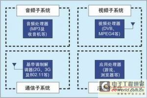
Figure 1: An example of a modular architecture with 4 subsystems.
A flexible architecture should include multiple subsystems that can be upgraded individually and have minimal impact on other modules. Each subsystem supports specific functions that have evolved independently from other functions (for example, wireless technologies that can independently evolve from video functions, etc.).
Figure 1 shows an example of a modular architecture using 4 subsystems. One of the subsystems is dedicated to communication and generally uses the baseband modem as the core; the other subsystem is used for the application and the application processor is the core (such as running 3D games or supporting PDA functions, etc.); the third subsystem is used to provide and video Broadcast (DMB or DVB-H) connection; the fourth subsystem is dedicated to audio processing (such as support for MP3 player functions, etc.).
These subsystems can be used to build certain platforms. Entry-level platforms may only use one of these modules (for example, application modules for PDAs, communication modules for mobile phones, and audio modules for MP3 players, etc.). More advanced platforms may use two, three, or even four modules based on specific functions and markets.
In this modular architecture, each module can be upgraded individually. For example, the communication module can be upgraded to support different wireless standards (from GPRS to W-CDMA, etc.), or upgrade existing protocols (eg, add HSDPA to existing W-CDMA baseband, etc.) Similarly, the application subsystem can be upgraded to support various functions supported by wireless standards (such as games and OS upgrades, etc.).
To connect subsystems with a time-tested interface In order to minimize the impact of each upgrade, each subsystem must be connected to other subsystems through an interface (which will be used on the next generation chipset) and can support the next generation Sufficient throughput required by the platform.
Each subsystem usually takes a processing device as the core (such as ASIC, DSP, GPP, etc.). Today, most of these processors lack such an interface: the serial interface is too slow to support the throughput requirements of new standards such as 3G, video, or 802.11; high-speed interfaces usually involve proprietary protocols, which are not only found in chip vendors Compatibility is not provided, and a lot of software changes and verification work are required each time the module is upgraded.
The memory bus is a good interconnection option. It not only supports all processors but also supports memory interfaces in the future, and the achieved bandwidth is also higher than the current requirements (the access time bandwidth of 55vns on the x16 bus can reach 290Mbps) . The two memory buses can be connected together by a two-port interconnect.
A dual-port interconnect is a memory-mapped device that allows two processing units to independently access a common memory space. It allows these processing units to exchange data through their memory bus and utilize standard read and write operations. Figure 2 shows an example of a dual-port interconnected baseband modem and video processor.
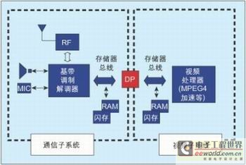
Figure 2: Block diagram of a mobile phone with two ports to connect two subsystems.
The dual port also allows upgrading existing systems by adding processing units to the existing architecture. In the example shown in Figure 2, the communication subsystem can be used as an existing system. Adding a new processor does not require major changes to the existing system, because the original processor can only "feel" the addition of new memory on its bus. One port of the dual port is connected to the memory bus of the existing processor, while the other port is connected to any type of device with an SRAM interface. These devices can include any type of processor (such as adding games, MP3, video, and even PDA functions) or modems (such as adding new communication bands, 3G acceleration, 802.11 connections, or video broadcasting, etc.).
In addition to the modular strategy, which can be upgraded with a shorter development time, the modular architecture also maximizes the reuse of IP developed for specific subsystems. By using similar modules to build across multiple platforms, the entire series can evolve into different available modules.
Figure 3 shows a mobile phone series based on this modular approach, in which a baseband chip is used in the simplest design, and then different application processors are added through a dual-port interconnect to enhance the function multiple times to create other new products. The dual-port interconnection can add two completely different application processors to the baseband processor with minimal changes. This not only creates a market for the new platform and makes it costly different, but also supports other applications that use the same communication module.
When developing the next-generation baseband, the previously developed application IP can be reused by only upgrading the communication subsystem while keeping the application unchanged. With this method, the existing architecture can be moved from one frequency band (eg GPRS) to another frequency band (eg CDMA) with minimal software and system architecture modifications.
Cypress MoBL dual-port dual-port is by far the most flexible interconnect between processors. By providing a standard SRAM interface for connection to existing memory buses, it not only enables existing processors to connect to almost any other processor, but also provides high bandwidth and simplifies and reduces communication software overhead.
Cypress (Cypress) semiconductor company uses its expertise in dual-port architecture and low-power technology to build a low-cost MoBL (More Battery Life) dual port designed specifically for mobile platforms. Cypress MoBL dual ports can also meet the requirements of other aspects of the new handheld device architecture.
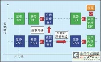
Figure 3: Mobile phone system with a modular architecture strategy.
In terms of power, Cypress's MoBL's low-leakage technology enables the dual-port standby power consumption to be as low as 3.6uW at 1.8V. As the market is flooded with various baseband processors and other processors, it also supports multiple I / O voltages (1.8V, 2.5V, and 3V).
In addition, as the bandwidth requirements for wireless systems continue to increase. Wireless systems now also require non-cellular technologies such as 802.11b that can support data rates up to 11Mbps. The standard low-rate serial interconnects available on some processors are often difficult to provide the required bandwidth, and Cypress MoBL dual ports provide fast access on the x16 bus with an execution time of 35ns, throughput up to 400Mbps, more than 3G, The data rate required for WiFi or video broadcasting.
Small footprint is another requirement. Cypress MoBL dual ports can be provided in bare die or in a small 6 × 6mm 0.5mm pitch BGA package.
In terms of functionality, the Cypress MoBL dual port is comparable to any other Cypress asynchronous dual port. When two ports try to access the same memory space at the same time, they will give a "busy" signal to provide built-in arbitration. The mailbox function allows the two processors to send interrupt signals to each other simply by writing to specific locations, which can be used to send data downloadable signals to other processors.
Mobile phone system designers hope to reduce the number of GPIO pins, which are used to drive extremely simple functions such as reading some external DIP switches or lighting LEDs. Cypress MoBL dual ports enable some of the above signals to reach the processor from the outside by incorporating input read registers and output drive registers in their characteristics. The input read register (IRR) captures the status of two external binary devices (such as DIP switches) into a specific memory space. By simply reading the dual port, any processor can monitor the status of these two devices. The output drive register (ODR) can drive up to 5 interrupt signals, which allows any processor to control up to 5 external devices by writing data only at specific locations on the dual ports.
To maintain competitiveness, portable equipment OEMs are now adopting a modular design strategy to enable them to quickly upgrade platforms and shorten the time to market for new mobile phones. Dual ports make this strategy possible by providing high throughput and memory-mapped interconnects. It allows the creation of multiple subsystems that can evolve individually and communicate with each other through their memory interfaces. In response to this new demand, Cypress has designed a new MoBL dual port dedicated to such applications and made it a low-power dual-port device.
Optical Socket Panel, also known as optical fiber panel or information panel.The main function of the panel is to fix modules and protect cables at the information outlet.Optical Socket Panel is widely used as a termination point for the feeder cable to connect with drop cable. The fiber splicing, splitting, distribution can be done in this box, and meanwhile it provides solid protection and management for the FTTx network building. It can be used indoor or outdoor.
Optical Socket Panel
Optical Patch Panel,Fiber Optic Patch Panel,Fiber Optic Panel,Optical Socket Panel
Chengdu Xinruixin Optical Communication Technology Co.,Ltd , https://www.xrxoptic.com