In the design of electronic systems, in order to avoid detours and save time, the anti-interference requirements should be fully considered and avoided, and remedial measures against interference should be avoided after the design is completed.
There are three basic elements that form interference:(1) Interference source refers to the component, device or signal that generates interference. It is described in mathematical language as follows: du/dt, where di/dt is large, it is the source of interference. Such as: lightning, relays, thyristors, motors, high-frequency clocks, etc. may become sources of interference.
(2) Propagation path refers to the path or medium that interferes with the propagation from the interference source to the sensitive device. Typical interference propagation paths are conduction through the wires and radiation from the space.
(3) Sensitive devices refer to objects that are easily disturbed. Such as: A / D, D / A converter, microcontroller, digital IC, weak signal amplifier.
The basic principle of anti-interference design is to suppress the interference source, cut off the interference propagation path, and improve the anti-interference performance of sensitive devices. (similar to the prevention of infectious diseases)
1 suppression interference source
To suppress the interference source is to reduce the du/dt, di/dt of the interference source as much as possible. This is the most important and most important principle in anti-jamming design, and it often has a multiplier effect. Reducing the du/dt of the interference source is mainly achieved by connecting capacitors across the interference source. Reducing the di/dt of the interferer is achieved by connecting the inductor or resistor in series with the source loop and adding a freewheeling diode.
(1) The relay coil increases the freewheeling diode to eliminate the back EMF interference generated when the coil is disconnected. Adding a freewheeling diode will delay the turn-off time of the relay. After the Zener diode is added, the relay can move more times per unit time.
(2) Connect the spark suppression circuit at both ends of the relay contact (usually RC series circuit, the resistance is generally selected from a few K to tens of K, and the capacitor is selected as 0.01uF) to reduce the influence of spark.
(3) Add a filter circuit to the motor, pay attention to the capacitor and inductor leads as short as possible.
(4) Each IC on the board should be connected with a high frequency capacitor of 0.01μF ~ 0.1μF to reduce the impact of the IC on the power supply. Pay attention to the wiring of high-frequency capacitors. The wiring should be close to the power supply terminal and be as short and as short as possible. Otherwise, it will increase the equivalent series resistance of the capacitor, which will affect the filtering effect.
(5) Avoid 90-degree fold lines during wiring and reduce high-frequency noise emission.
(6) The RC suppression circuit is connected to both ends of the thyristor to reduce the noise generated by the thyristor (this thyristor may break down when the noise is severe).
According to the propagation path of interference, it can be divided into two types: conducted interference and radiated interference.
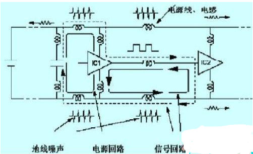
Conducted interference is the interference that propagates through a wire to a sensitive device. The high-frequency interference noise and the frequency band of the useful signal are different, and the propagation of the high-frequency interference noise can be cut off by adding a filter to the wire, and sometimes the isolation optocoupler can be added. Power supply noise is the most harmful, so pay special attention to handling. Radiation interference refers to interference that propagates through a spatial radiation to a sensitive device. The general solution is to increase the distance between the interferer and the sensitive device, isolate them with ground and add a shield to the sensitive device.
Common measures to cut off the interference propagation path are as follows:(1) Fully consider the impact of the power supply on the microcontroller. The power supply is well done, and the anti-interference of the entire circuit is solved. Many single-chip microcomputers are very sensitive to power supply noise. It is necessary to add a filter circuit or a voltage regulator to the power supply of the single-chip microcomputer to reduce the interference of the power supply noise on the single-chip microcomputer. For example, a magnetic bead and a capacitor can be used to form a π-shaped filter circuit. Of course, a 100Ω resistor can be used instead of the magnetic bead when the condition is not high.
(2) If the I/O port of the MCU is used to control noise devices such as motors, isolation should be added between the I/O port and the noise source (increasing the π-shaped filter circuit). Control noise devices such as motors, and add isolation between the I/O port and the noise source (increasing the π-shaped filter circuit).
(3) Pay attention to the crystal wiring. The crystal oscillator and the MCU pins are placed as close as possible, and the clock region is isolated by the ground wire. The crystal oscillator case is grounded and fixed. This measure can solve many difficult problems.
(4) Reasonable division of the circuit board, such as strong and weak signals, digital and analog signals. Keep interference sources (such as motors, relays) away from sensitive components (such as microcontrollers) as much as possible.
(5) Separate the digital zone from the analog zone with a ground wire, separate the digital ground from the analog ground, and finally connect it to the power ground at one point. A/D and D/A chip wiring are also based on this principle. This requirement has been considered when the manufacturer assigns A/D and D/A chip pinouts.
(6) The ground wire of the MCU and the high-power device should be grounded separately to reduce mutual interference. Place high-power devices on the edge of the board as much as possible.
(7) Anti-interference components such as magnetic beads, magnetic rings, power supply filters, and shields can be used in key areas such as I/O ports, power lines, and circuit board connectors to significantly improve the anti-jamming performance of the circuit.
3 Improve the anti-jamming performance of sensitive devices
Improving the anti-interference performance of sensitive devices refers to the method of minimizing the pickup of interference noise and recovering from an abnormal state as soon as possible from the sensitive device side.
Common measures to improve the anti-jamming performance of sensitive devices are as follows:(1) Minimize the loop loop area during wiring to reduce induced noise.
(2) When wiring, the power and ground wires should be as thick as possible. In addition to reducing the voltage drop, it is more important to reduce the coupling noise.
(3) For the idle I/O port of the MCU, do not hang it, ground it or connect it to the power supply. The idle ends of other ICs are grounded or connected to the power supply without changing the system logic.
(4) The power supply monitoring and watchdog circuit for the single-chip microcomputer, such as IMP809, IMP706, IMP813, X25043, X25045, etc., can greatly improve the anti-interference performance of the whole circuit.
(5) Under the premise that the speed can meet the requirements, try to reduce the crystal oscillator of the single-chip microcomputer and select the low-speed digital circuit.
(6) The IC device is soldered directly on the circuit board as much as possible, and the IC holder is used less.
What is a Capsule Slip Ring?
Capsule slip rings are a type of electrical connector that are used to transfer power and data between two rotating objects. They are commonly used in applications where there is a need to send or receive signals from a stationary object to a rotating one, or vice versa.
How Does it Work?
Capsule slip rings work by using a series of electrical contacts that rotate with the object on which they are mounted. These contacts are spaced evenly around the circumference of the ring, and as they rotate they make and break contact with corresponding contacts on the other object. This allows power and data to be transferred between the two objects without any interruption.
Advantages of Capsule Slip Rings
There are several advantages to using capsule slip rings in place of other types of electrical connectors.
For example, the rotation of the contacts causes them to be freely accessible and therefore free from dust and debris. This makes them ideal for applications where connector maintenance is often a problem.
Because the contacts are freely accessible, they can be readily replaced if a fault occurs. They also have very low electrical resistance, making them ideal for transmitting radio frequency signals. Because of the low resistance, this type of connector is often used in high-speed data transmissions.
This type of Conductive Slip Ring is similar to the shape of a hat. The brim part is a flange with a conductive slip ring. The function of the flange is to facilitate installation. It is connected to electrical equipment through the fixing hole of the flange. It can be firmly installed on the equipment. Therefore, the stator of the cap-type slip ring is generally fixed by the outer layer with a flange, and the inner part is the rotor with the inner shaft rotating. The stator and the rotor are not fixed, and the details will be different according to the installation method.

Capsule Slip Ring,Split Ring Motor,Slip Ring Motor Connection,Slip Rings In Synchronous Motor
Dongguan Oubaibo Technology Co., Ltd. , https://www.sliprob.com