I believe every engineer who has used HFSS has a question or has a question: How can I use HFSS to calculate quickly and accurately? For the user, each engineer encounters different engineering problems, and engineering experience cannot be directly copied. For software, as the HFSS version is updated, HFSS algorithms are more and more, corresponding to different application scenarios. The algorithm. Therefore, speed and accuracy can be balanced only if the actual engineering problem fits the appropriate algorithm. Based on the understanding of software algorithms, engineers can make good algorithm choices for their own needs.
Due to the rapid development of computers in the world today, the subject of computational electromagnetics has also been greatly developed. As shown in Figure 1, from a large perspective, we have divided the computational electromagnetics into precise full-wave algorithms and high-frequency approximations. The algorithm, which is divided into a large number of algorithms under each category, is combined with HFSS software. Through ANSYS's unremitting research and development and strategic acquisition for more than 40 years, HFSS has FEM, IE (MoM), DGTD, and so far. Algorithms such as PO and SBR+ will be introduced one by one for each algorithm and application scenario. I believe that after reading this article, you should have a deeper understanding of HFSS algorithms and application scenarios.
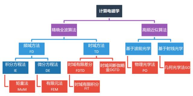
Figure 1 Computational electromagnetics
Algorithm Introduction Full Wave Algorithm - Finite Element Algorithm (FEM)
The finite element algorithm is the core algorithm of ANSYS HFSS. It has more than 20 years of commercial history and is the most mature and stable 3D electromagnetic field solver in the industry. The advantage of the finite element method is its excellent structural adaptability and material adaptability. Full consideration of material properties: skin effect, dielectric loss, and frequency-changing materials; it is the best tool for accurately solving the complex structure of complex materials. The finite element algorithm uses a tetrahedral mesh and can be well restored for simulated objects.
The dominating equation of FEM algorithm is shown in the figure below:
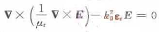
Fig. 2 FEM algorithm governing equation
The HFSS finite element algorithm can support adaptive meshing, mesh encryption, and curve mesh in meshing. It supports tangent vector basis function, mixed order base function and direct method, iterative method, and region decomposition when solving. The powerful matrix solution technique.
In the application field, HFSS is mainly used to solve complex structures, especially for solving some internal problems, and is more suitable for solving finite element methods than application scenarios such as high-speed signal integrity analysis, array antenna design, cavity problems, and electromagnetic compatibility.
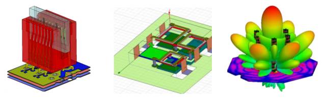
Figure 3 FEM algorithm application scenario
The finite element algorithm combined with the HPC module of ANSYS company, ANSYS HFSS finite element algorithm can be used to calculate the size of electric objects, and greatly enhance the efficiency of simulation engineers. For broadband problems, FEM has introduced broadband adaptive meshing, which greatly improves simulation accuracy.
Full Wave Algorithm - Integral Equation Algorithm (IE)
The integral equation algorithm is based on the integral form of Maxwell's equations and is also based on the Green's function, so it can automatically satisfy the radiation boundary conditions. It has great advantages for the radiation problem of simple models and materials, but the original integral equation method calculates too much. Large, it is difficult to use in actual numerical calculation. To solve this problem, the IE algorithm in HFSS provides two acceleration algorithms, one is ACA acceleration and the other is MLFMM, and the distribution is for different application types. The ACA method is based on the acceleration technology at the numerical level and has better universality. However, the efficiency is slightly worse than that of the MLFMM. The MLFMM algorithm is based on acceleration at the grid level, and has higher efficiency for metallic materials and loose structures.
The dominating equation of IE algorithm is shown in the figure below:
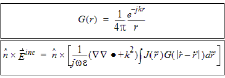
Fig. 4 IE algorithm governing equation
The IE algorithm is a three-dimensional moment method integral equation technique that supports triangle meshing. The IE algorithm does not need to define the radiation boundary conditions like the FEM algorithm, and it is mainly used in HFSS to efficiently solve the problem of size and open structure of the electric current. Like the HFSS FEM algorithm, it supports adaptive grid technology and can solve customer problems with high accuracy and efficiency. It also supports linking FEM field sources to IE for solving. The HFSS-IE algorithm has high adaptability to metal structures. Its main application areas are antenna design, antenna layout, RCS, EMI/EMC simulation and other directions.
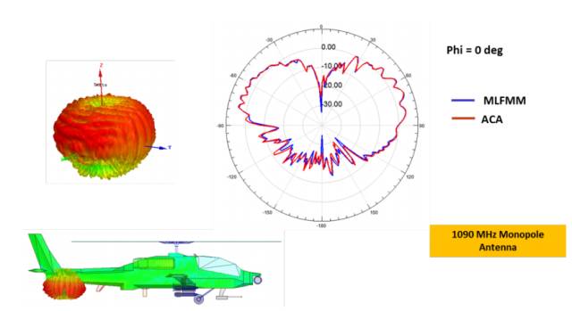
Figure 5 HFSS-IE antenna layout simulation
High Frequency Approximation Algorithm-PO Algorithm
The FEM algorithm and the IE algorithm are accurate full-wave algorithms, and the use of an accurate full-wave algorithm will cause a decrease in efficiency in the case of an oversized electrical dimension. For large size problems, ANSYS introduced the PO (Physical Optics) algorithm. The PO algorithm is a high-frequency algorithm and is very suitable for solving such problems. It has very good efficiency advantages in solving problems.
The main principle of the PO algorithm is to generate the induced current in the radiation area, and set the current in the shadow area to zero current, regardless of ray tracing or multiple reflections. The incident wave is used as the excitation source and the plane wave or link FEM (IE) field data is taken as the Feed. However, due to the fact that multiple reflections and diffraction of radiation are not considered, the calculation of the electromagnetic field of an object with a large physical size and a uniform structure is generally performed. Compared with the requirement of the accuracy, the efficiency of the full-wave algorithm is significantly improved. Such as the antenna layout on a large platform, a large reflector antenna and so on.
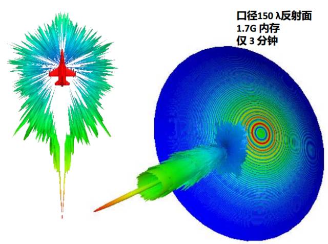
Figure 6 HFSS-PO antenna layout simulation
High Frequency Approximation Algorithm-SBR+ Algorithm
The PO algorithm can solve the calculation of the super-large electrical dimension problem, but because physical objects such as multiple reflections are not considered, it is mainly used for the calculation of the electromagnetic field with uniform physical structure. For complex structures and large electrical dimensions, ANSYS introduced the SBR+ algorithm through the acquisition of Delcross (Savant Software). SBR+ considers crawl wave radiation based on the SBR algorithm (the antenna emits a beam and “plots†the PO current on the surface). (Track rays along the surface), physical diffraction theory PTD (correction of PO current at the edge), consistent diffraction theory UTD (diffracted ray emission along the edge, draw current in shaded areas), so the SBR+ algorithm is a high frequency The ray method has a very efficient speed and at the same time has a very good precision, which is very good in the antenna layout of a large platform.
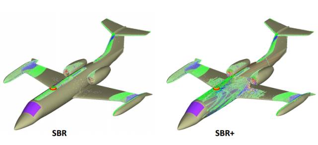
Figure 7 Comparison between SBR and SBR+ algorithms
SBR+ supports importing far-field radiation patterns or current sources from FEM and IE, and also supports the import of corresponding test data. SBR+ algorithm is mainly used for antenna installation analysis, supports multi-core, GPU and other parallel solving methods and most tasks can be lower than Completed with 8 GB of memory.

Fig. 8 Simulation comparison between FEM algorithm and SBR+ algorithm
Hybrid Algorithm (FEBI, IE-Region, PO-Region, SBR+ Region)
In the foregoing, various algorithms in the frequency were introduced and the application scenarios of various algorithms were described. Many engineering problems encountered include both complex structural physics and oversized physics, such as antenna layout problems on new energy vehicles. For simulation, the best accuracy is to use the full-wave algorithm. The fastest speed is to use the approximate solution. For this problem, ANSYS integrates FEM algorithm, IE algorithm, PO algorithm, SBR+ algorithm, etc. algorithm. In an application case, using the advantages of different algorithms to avoid the disadvantages of different algorithms can greatly improve the efficiency of the algorithm and become the necessary algorithm to solve large-scale complex problems in the frequency domain.
FEM and IE in HFSS can be solved by IE Region and FEBI boundary. FEM and PO and SBR+ algorithms can be mixed by adding PO Region and SBR+ Region. The use of hybrid algorithm can expand the scope of HFSS.
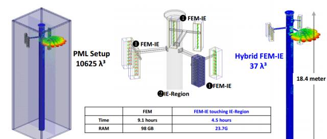
Fig. 9 Comparison between FEM and IE hybrid solution and FEM
Time domain algorithm-transient algorithm
The HFSS time domain solution is a three-dimensional full-wave electromagnetic field simulator based on the discontinuous Galerkin method (DGTD). Based on the tetrahedral finite element technique, the same adaptive meshing as the HFSS frequency domain solver can be obtained. The sub-precision, this technology makes the refinement precision of HFSS become the electromagnetic field industry standard. This technology complements the frequency domain solver technology of HFSS and helps engineers to more deeply understand the electromagnetic performance of the devices they design.
The Transient algorithm dominates the equation as shown below:
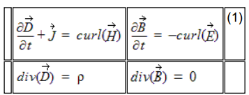
Figure 10 Transient algorithm dominance equation
Using the HFSS-Transient algorithm, engineers can use short-pulse excitations to investigate applications such as ground penetrating radar, electrostatic discharge, electromagnetic interference, and lightning strikes. They also include time-domain reflection impedances and transient field displays with short-term excitation. It's done.

Figure 11 Transient algorithm application scenario
Resonance Analysis - Eigenmode Algorithm
The resonant characteristic is that each structure has an inherent electromagnetic resonance. The resonant mode, frequency, and quality factor are related to the size of the structure. These resonances may be either the source of the interference amplifier or the noise receiver of the sensitive circuit. Resonance can lead to signal integrity, power integrity, and electromagnetic compatibility issues, so understanding the resonance helps to enhance design reliability.
The Eigenmode algorithm dominates the equation as shown below:
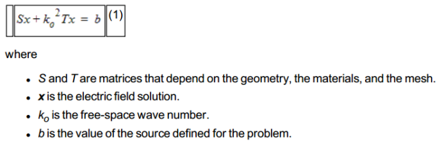
Figure 12 Eigenmode algorithm dominance equation
In HFSS, the eigenmode algorithm can be used to calculate the three-dimensional structural resonance mode, and the resonant voltage fluctuations in the graphical space can be presented, and the inherent resonant characteristics of the structure can be analyzed. Based on the results of the resonant analysis, the device layout and PCB stack layout in the chassis are guided to improve the electromagnetic compatibility.
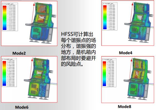
Figure 13 Eigenmode algorithm application scenario
to sum up
There are different kinds of algorithms in HFSS, full wave algorithm, approximate algorithm and time domain algorithm. Engineers can choose different algorithms (highest accuracy and highest efficiency). First of all, for the frequency domain algorithm, the scope of use is shown in Fig. 14. Usually, the FEM algorithm and IE algorithm are suitable for small and medium size problems. For large problems, the FEM/IE runtime/memory requirements are very large. The PO method is suitable for solving large electrical dimension problems, but The complexity of the problem is limited, usually it usually cannot provide the precision that the customer expects, but it is a good choice for a uniform object; SBR+ algorithm is suitable for solving the problem of large electrical dimension, and it can also provide good precision and speed for complex structures; In view of the computational problems of existing small-sized complex structures and the calculation of large-size layouts, the hybrid algorithm is a good choice. Transient algorithm is suitable for solving time-related electromagnetic field problems, such as ESD, TDR, etc.; Eigenmode algorithm is specifically for resonance simulation.
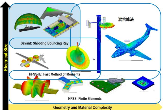
Figure 14 HFSS frequency domain algorithm selection
About RF Hundred Flowers Lake
Focusing on RF microwave/high-frequency high-speed technology, it is the largest technology exchange and information sharing platform in this field. Developed by senior RF expert, "ADS2008/2011 RF Circuit Design and Simulation Example" "HFSS RF Simulation Design Encyclopedia" editor Xu Xingfu. The number 80000 attention, 13000 plus group (Dr. 2000), WeChat group includes a number of general managers, research and development directors, professors, scholars, IEEE Fellow, etc., to gather the global Chinese radio frequency elite.
The KSPOWER brand H series - triac dimmable led driver provides phase cut dimmable constant voltage LED Drivers with IP65 IP67 rating environment protection. The dimmable LED driver can make the output wattage of MAX 320W and accept 12Volt, 24Volt, 36Volt and 48Volt output voltage optional. The under cabinet lighting transformer is Class 2 Class P rated, offers 5 Years warranty and both UL/cUL, FCC CE ENEC GS Listed and SELV style enclosures. The phase dim LED driver is flicker free design and protections for short circuit, over load, over voltage and over temperature. The triac dimmable led driver use low profile aluminum case with junction box makes pwm dimming led driver the power solutions for LED strips, LED sign, billboard and landscape lighting. The dimmable led driver 12v elv driver is designed to operate with any standard brand dimmer switch, like Lutron dimmer etc, perfectly suitable for indoor or outdoor use and outstanding led dimming performance.
led transformer 12v, dimmer driver, under cabinet lighting transformer, led panel light driver, led light supply
Shenzhenshi Zhenhuan Electronic Co., Ltd , https://www.szzhpower.com