Meter wave radar frequency band is 30~300MHz, wavelength is 1m~10m, meter wave radar belongs to long wave radar, it has its own transmitter, it is mainly used for long-distance detection, the threat to fighters is relatively small. The detection of stealth aircraft is accomplished through multiple batches of continuous power scans. However, due to its own radiation source, it is easy for the other party to discover and implement effective attacks.
Mipo radar worksThe Stealth fighter mainly reduces the radar's detectability through the appearance of stealth design and absorbing coating. However, as far as all stealth fighter planes are concerned, the so-called “full stealth†capabilities of all-round and all-electromagnetic bands are still not realized. Especially when fighter planes perform missions, mounted missiles or external fuel tanks do not possess stealth performance, and they greatly increase. The possibility of a fighter being detected by the radar. And even without the plug-in, stealth fighter can only achieve the stealth of the microwave radar in the front and the abdomen. The stealth electromagnetic wave band is mostly in the range of 0.3~29 GHz, and the meter wave radar just avoids the stealth band of the stealth fighter. The reason why stealth fighters can be detected.
It is because Mibo Radar “naturally†possesses the “expertise†of discovering stealth fighter planes. Its detection range is far away, its volume and weight are not large, and it is affected by weather conditions with low electronic antagonism and is suitable for being placed on the ground. Mobile deployments on sea-based and space-based platforms have led many military professionals to believe that, in contrast, Mibo Radar has a better overall advantage and should shoulder the heavy responsibility of anti-stealth fighters. However, the traditional Mipo radar uses a simple Yagi antenna or an old mesh antenna. The disadvantages are poor resolution, low detection accuracy, inability to measure height, and limited target recognition capability, and it is difficult to eliminate the effects of ground reflections. The low-altitude detection capability is weak, the coverage airspace is not continuous, the anti-interference ability is insufficient, and the position is poorly adaptable. These problems are also an important reason for the stagnation of Mibo Radar's development. They also determined that Mipra radar’s “vision†does not increase if it is not improved. It can only focus on air defense warnings and cannot be used for weapon guidance. It is impossible to provide high-quality tracking of stealth fighters and it is difficult to become the core radar in the current anti-stealth fighters.

In the influence of the ground environment on the radar coverage, the ground cover is an important aspect. If there are tall buildings around the radar or the mountain terrain exists, it may form a certain range of shadow blindness for the radar. Radar detection power. Without considering the diffraction effect, the radar will not be able to detect the target below the shielding angle.
As a long-range early-warning radar, the meter-wave radar needs to detect long-range targets. In order to make the model more accurate, the influence of the curvature of the earth needs to be considered, and a spherical reflection model is used. In the spherical reflection model, the relationship between the target elevation angle and target distance, height, radar erection height and other parameters
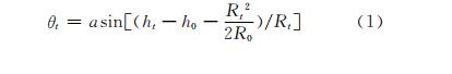
Where: θt is the target elevation; ht is the target altitude; ho is the radar phase center height; Rt is the target distance; R0 is the equivalent Earth radius.
When the target height is 20000m and 10000m, the influence of different shielding angles on the radar range is shown in Figure 1.
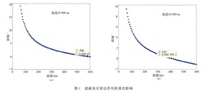
Therefore, when choosing a radar to set up positions, it is necessary to study the characteristics of the ground around the position, avoid the features that may mask the radar in the main battle direction, and take into account other directions to ensure that the radar power is fully utilized.
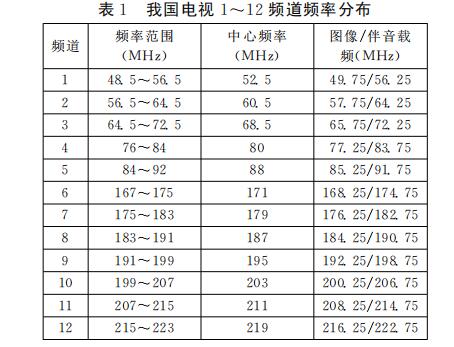
2, the same band interference effectsMipo radar works in the VHF band, which is usually occupied by electronic devices such as communications, navigation, and television. Therefore, the meter radar is susceptible to unintentional interference with these civilian devices. Taking TV channel interference as an example, according to GB/T14433-93 "Technical Provisions for Coverage Network of Color Television Broadcasting", the frequency distribution of channels 1 to 12 of China's Mi Band wireless TV is shown in Table 1. These interferences in the same frequency band will affect meters. Wave radar produces noise interference or false target interference.
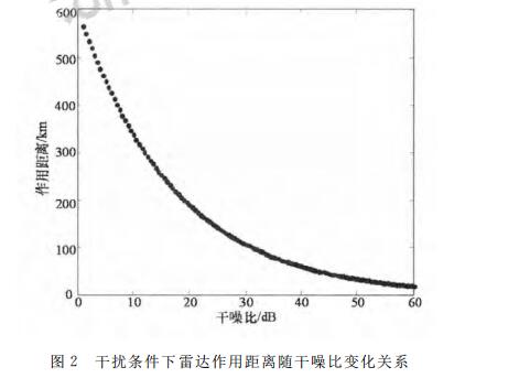
When considering noise interference, according to the radar distance equation, the relationship between the radar action distance and the noise-to-noise ratio under interference conditions is shown in Figure 2. It can be seen that noise interference seriously affects the radar's range of action. Therefore, when selecting radar arrays, these same-band interferences should be avoided as much as possible.
Mipra radar has a low operating frequency band and a wide beamwidth, which is easily affected by the reflection of the ground (water) surface. Because of the interference of the multi-path signal of the ground (water) surface, the vertical surface lobe of the antenna will change. The amplitude lobe function of the vertical plane of the free space antenna is f0(θ,θ0), where θ0 is the maximum value of the lobe. Point angle; δ is the wave path difference between the direct wave and the reflected wave at the target; Sd is the electric field strength of the direct wave at the target; Sr is the electric field strength of the reflected wave at the target; φd is the free space antenna lobe in the direct The phase at the wave elevation angle θd; φr is the phase of the free space antenna lobe at the direct wave elevation angle θr; f0(θd,θ) is the amplitude value of the free space antenna lobe at the direct wave elevation angle θd; f0(θr,θ ) is the amplitude value of the free space antenna lobe at the direct wave elevation angle θr; Ï is the amplitude of the ground reflection coefficient; φg is the phase of the ground reflection coefficient.
Here, only the effects of ground conductivity, ground roughness, etc. are considered, and the influence of the curvature of the earth is not considered. According to the superposition principle, the electric field intensity at the target is a superposition of the direct wave electric field strength and the reflected wave electric field strength, expressed as follows:

Known by electromagnetic theory:

Substituting Eqs. (2) and (3) into Eq. (1) results in the lobe of the antenna taking into account multipath effects:

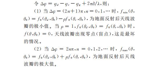
The simulation of radar beam splitting without considering ground reflection and different height conditions is shown below, as shown in Figure 3 to Figure 8. The simulation conditions are: operating frequency 60 MHz, beam width 6.5°, and radar erection heights of 40 m, 100 m, 200 m, 300 m, and 400 m, respectively.

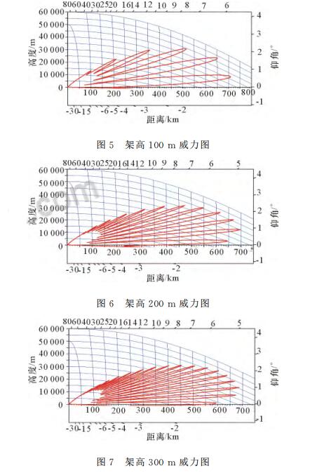
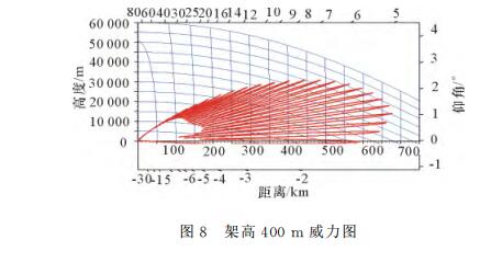
From the simulation results, it can be seen that under different height conditions, the splitting of the lobes is significantly different, resulting in different power coverage. When selecting positions, radar power coverage can be evaluated based on radar performance parameters and erection height. In the case of high altitude, working parameters matching the erection height are used to achieve full utilization of radar power.
ConclusionThe appearance of stealth aircraft poses a serious challenge to air defense radar systems in various countries, forcing countries to vigorously develop and deploy meters wave radar to cope with the impact of interference analysis technology of road simulation on the impact of receiver interference on receiver performance.
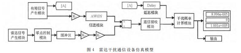
Especially for military applications, currently modern military-use electronic frequency equipment generally has anti-jamming measures. The same interference signal enters two similar receivers using different anti-jamming measures. Although the same interference power enters the receiver, it will produce Different interference effects require more elaborate analysis methods. For the application scenario where the amount of equipment to be analyzed is very large, preliminary analysis may be performed using deterministic analysis technology first, and then the interference analysis technology based on the interference link simulation may be further analyzed in order to achieve a balance between analysis efficiency and analysis accuracy.
Screw Terminal Connector,Pcb Screw Terminal,Screw Terminal Block Connector,Screw Type Terminal Blocks
Cixi Xinke Electronic Technology Co., Ltd. , https://www.cxxinke.com